简体中文
简体中文  English
  日本語
日本語  한국어
한국어  Français
  Deutsch
  Español
  Português
  Русский
  العربية
  ไทย
ไทย  Tiếng Việt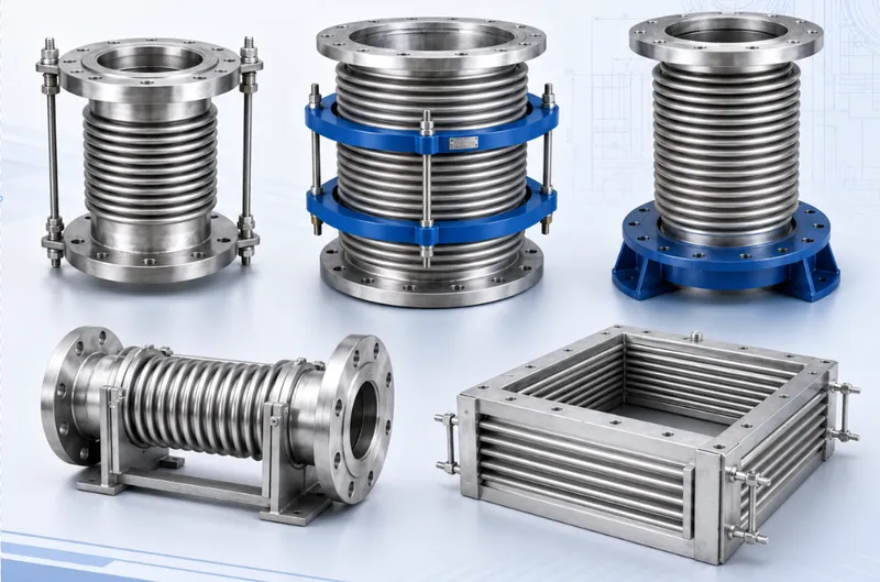

Pipe Connection and Expansion Joint Solutions for Pump Station Projects
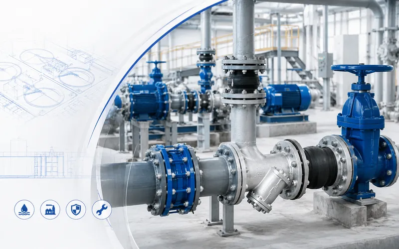
Pump station piping does more than convey water or other fluids. It must also accommodate equipment vibration, installation tolerances, valve maintenance, axial forces, wall penetrations and long-term operating requirements. A system based entirely on rigid pipe sections and fixed flanges may not provide the adjustment and maintenance flexibility required at every connection point.
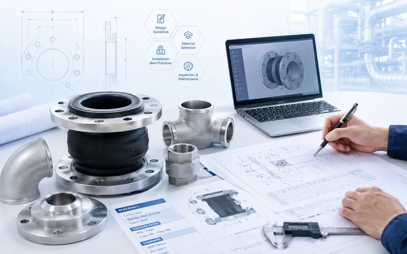
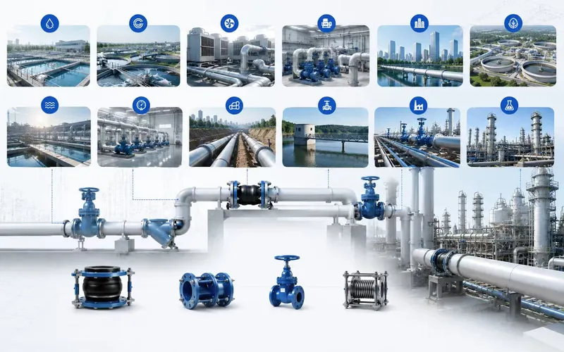
This guide explains the typical application of rubber expansion joints, dismantling joints, limit expansion joints, flange adaptors, steel flexible couplings, waterproof wall sleeves and related pipeline products in water-supply, wastewater, drainage and industrial pumping stations.
1. Common Piping Challenges in Pump Stations
Pumps, valves, strainers, check valves, headers and wall penetrations are often installed within a limited plant-room area. Each connection point may have a different mechanical, hydraulic and maintenance requirement.
Pump Vibration and Noise Transmission
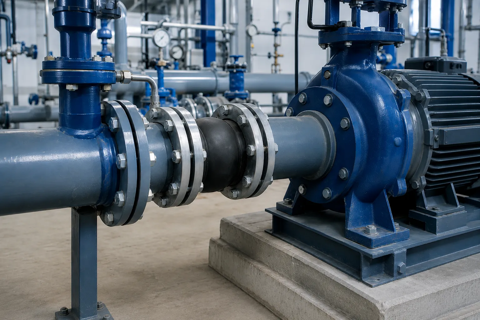
Mechanical vibration generated by operating pumps may be transmitted through suction and discharge piping to supports, structural walls and adjacent equipment. A properly selected flexible connector may help reduce this transmission, but it must not replace correctly designed pipe supports or carry unsupported pipe weight.
Insufficient Space for Equipment Dismantling
Pumps, check valves, isolation valves and strainers require periodic inspection or replacement. When every pipe section has a fixed length, equipment removal may require cutting the pipe or moving adjacent components.
Installation-Length Tolerances
Differences between civil foundations, embedded items, equipment flanges and actual pipe alignment may create installation tolerances. An appropriate adjustable connector can provide controlled installation movement without redesigning the complete pipe assembly.
Pipeline Thrust and Transient Pressure
Pump starting and stopping, rapid valve operation and changing flow conditions may create transient pressure and axial forces. Anchors, guides, supports, restraint devices and force-transmission components should be considered as one complete system.
Wall and Tank Penetrations
Pump station inlet and discharge pipes commonly pass through walls, tanks or underground structures. The penetration must satisfy civil construction, waterproofing, sealing and pipe-movement requirements.
2. Typical Pump Station Connection Points
The following table provides a functional reference only. The final arrangement must be determined by the project designer.
| Position | Main Requirement | Products to Consider |
|---|---|---|
| Near the pump suction | Flexible connection, vibration isolation and installation adjustment | Rubber expansion joint or steel flexible coupling |
| Near the pump discharge | Vibration isolation and controlled movement | Rubber expansion joint with suitable restraint where required |
| Next to valves or equipment | Dismantling space, installation adjustment and force transmission | Double-flange dismantling joint |
| Flanged pipeline section | Controlled axial adjustment and movement limitation | Double-flange limit expansion joint |
| Plain-ended pipe to flanged equipment | Connection-system transition | Flange adaptor |
| Plain-ended pipe to plain-ended pipe | Flexible connection and outside-diameter tolerance | Steel flexible coupling |
| Wall or tank penetration | Structural protection and waterproof sealing | Rigid or flexible waterproof wall sleeve |
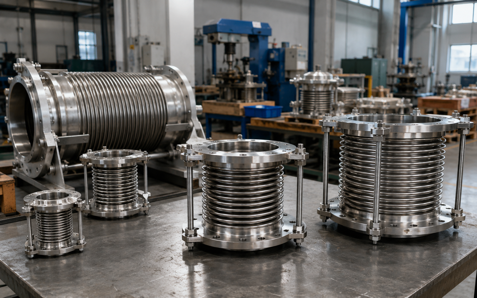
| Long pipeline with thermal movement | Thermal expansion compensation | Metallic bellows or another engineered compensator |
A typical discharge line may include a pump, a flexible connector, a check valve, an isolation valve, a dismantling component and a discharge header. The exact sequence should be determined according to hydraulic conditions, equipment instructions, maintenance clearance and piping loads.
3. Rubber Expansion Joints for Flexible Pump Connections
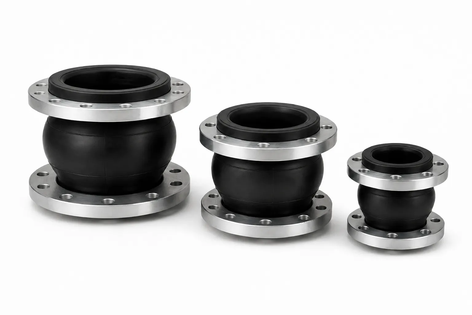
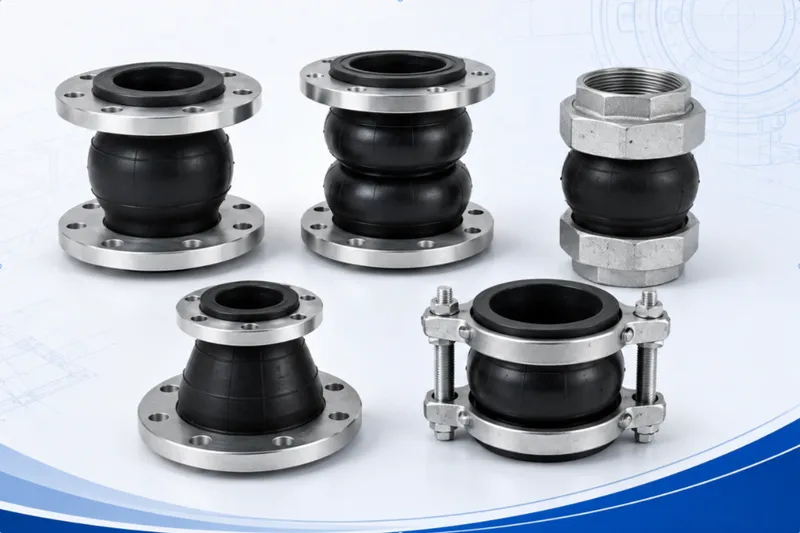
A rubber expansion joint normally consists of an elastomer body, reinforcing layers and metallic end connections. Within its specified capability, it can accommodate axial, lateral and angular movement while helping isolate a portion of mechanical vibration and noise.
Typical Applications
- Flanged pipework near pump suction or discharge connections;
- Circulating-water, water-supply and general industrial water systems;
- Locations where vibration transmission to adjacent piping should be reduced;
- Connections requiring limited flexibility for installation alignment.
Available Configurations
- Single-sphere rubber expansion joint: a compact design for common pump and equipment piping.
- Double-sphere rubber expansion joint: a two-arch construction requiring confirmation of installation length and system stability.
- Grooved rubber flexible coupling: intended for compatible grooved piping systems.
- Threaded rubber expansion joint: suitable for relatively small auxiliary pipe connections.
4. Double-Flange Dismantling Joints for Equipment Maintenance
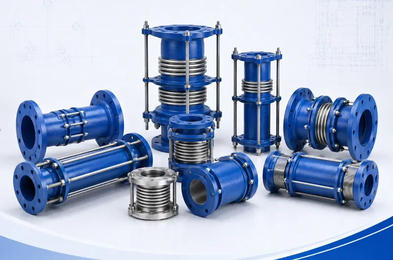
A double-flange dismantling joint generally consists of a main body, telescopic section, sealing arrangement, gland, flanges and longitudinal connecting bolts. It provides limited installation adjustment and transfers axial forces through its structural components.
Typical Locations
- Next to pump discharge valves and check valves;
- Beside large valves requiring periodic removal;
- At pumps, strainers and other flanged equipment connections;
- Where maintenance clearance is required in a compact pump room.
During maintenance, the adjustable section can provide clearance for removing a valve or equipment item, reducing the need for field cutting and rewelding. Installation length, flange standard, operating conditions and pipeline load requirements must be checked before selection.
5. Limit Expansion Joints for Controlled Axial Adjustment
A limit expansion joint uses sleeves, seals, glands and limit rods to provide controlled axial installation adjustment. The limiting structure helps control extension and reduce the risk of separation caused by excessive movement.
Common Types
- Single-flange limit expansion joint: one flanged end and one pipe or welding end.
- Double-flange limit expansion joint: two flanged ends for installation between valves or flanged pipework.
- Flanged loose-sleeve expansion joint: installation adjustment through a sliding sleeve and sealing system.
- Gland-type loose-sleeve expansion joint: sealing achieved by compressing the seal around the sleeve.
The available installation adjustment must not automatically be treated as unrestricted operating movement. The permitted movement, restraint arrangement and pipeline thrust must be confirmed by the system designer.
6. Flange Adaptors for Plain-Ended Pipes
A pump station may contain steel, ductile-iron, PVC or other plain-ended pipes. A flange adaptor can be considered where such a pipe must connect to a flanged valve, strainer, pump or item of equipment.
One end normally has a flange, while the other uses a gland, sealing ring and gripping arrangement around the pipe. The actual pipe outside diameter must be provided because nominal diameter alone does not determine the correct adaptor range.
Selection Information
- Actual pipe outside diameter and tolerance;
- Pipe material and surface condition;
- Equipment flange drilling and sealing face;
- Operating medium and corrosion-protection requirements;
- Whether additional axial restraint is required.
7. Steel Flexible Couplings for Plain-Ended Pipe Connections
A steel flexible coupling connects two plain-ended pipes and may accommodate a limited range of outside-diameter variation, installation tolerance and angular deflection. It is commonly considered for pump-room piping, inlet and outlet lines, rehabilitation projects and connections between existing pipe sections.
Sealing performance depends on the actual pipe outside diameter, pipe-surface condition, gasket selection and correct bolt tightening. Pipe ends should be prepared according to the installation instructions and should not have severe ovality, burrs, dents or excessive corrosion.
8. Waterproof Wall Sleeves at Structural Penetrations
Waterproof wall sleeves are used where pipelines pass through pump-room walls, tanks, underground structures or other waterproof construction. They provide an engineered opening, structural protection and sealing conditions around the pipe.
Rigid Waterproof Sleeve
A rigid construction can be considered where expected pipe movement is limited and the surrounding structure is relatively stable.
Flexible Waterproof Sleeve
A flexible construction can be considered where a higher sealing requirement or limited pipe movement must be accommodated.
Sleeve dimensions should be confirmed during the civil construction stage according to wall thickness, pipe outside diameter, elevation and sealing requirements.
9. Supporting Roles of Valves, Check Valves and Strainers
Pump station piping normally includes isolation valves, non-return devices and filtration equipment in addition to connection products.
- Isolation valves: isolate equipment or pipe sections during maintenance.
- Check valves: help prevent reverse flow after a pump stops.
- Strainers: intercept debris before it reaches pumps or downstream equipment.
Valve and strainer selection should match pipe size, medium, operating conditions, installation direction and maintenance clearance. Dismantling or expansion components should be positioned according to equipment-removal procedures and piping-load requirements.
10. Suggested Product Combinations for Different Pump Stations
| Application | Main Challenges | Products to Consider |
|---|---|---|
| Municipal water-supply station | Vibration, valve maintenance and flanged connections | Rubber joints, dismantling joints, check valves and isolation valves |
| Wastewater lifting station | Corrosion, debris and equipment removal | Medium-compatible rubber joints, dismantling joints, check valves and suitable coatings |
| Industrial circulating-water station | Continuous operation, vibration, temperature change and maintenance | Rubber joints, limit expansion joints, metallic compensators and valves |
| Water-treatment equipment skid | Multiple equipment interfaces and limited installation space | Rubber joints, flange adaptors and steel flexible couplings |
| Existing pump station rehabilitation | Different new and existing dimensions and site tolerances | Flange adaptors, dismantling joints, flexible couplings and customized connectors |
11. Information Required for Product Selection
To evaluate the connection and prepare a quotation, provide the following information where available:
- Pump station function and operating medium;
- Nominal diameter and actual pipe outside diameter;
- Operating pressure, design pressure and possible transient conditions;
- Fluid and ambient temperatures;
- Pipe and equipment flange standards;
- Required installation length and available space;
- Expected movement direction;
- Pipe material and coating requirements;
- Pump, valve and piping layout drawings;
- Supports, anchors and wall-penetration locations;
- Project specification and documentation requirements;
- Quantity, packaging method and destination port.
12. From Drawing Review to Delivery
- Application review: identify the pump station type, medium and operating conditions.
- Drawing review: locate pumps, valves, piping, supports and wall penetrations.
- Product matching: select suitable rubber joints, dismantling joints or expansion connectors for each location.
- Technical confirmation: check dimensions, connections, materials, flanges and coatings.
- Drawing or datasheet approval: confirm non-standard constructions before production.
- Manufacturing and inspection: manufacture and inspect according to the order and agreed requirements.
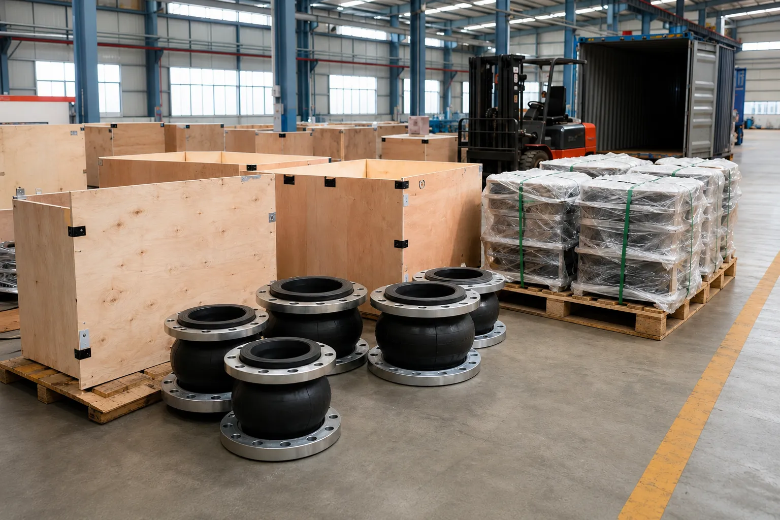
- Packaging and shipment: arrange packaging according to product size, transport method and destination.
- Installation-document support: provide agreed drawings, instructions or technical documents.
13. Frequently Asked Questions
Must rubber expansion joints be installed at both pump connections?
Not necessarily. The need and position should be determined according to the pump type, piping arrangement, vibration, suction conditions, pipe supports and project specification.
Can a rubber expansion joint support pipe weight?
No. The piping should have independent and properly designed supports. A rubber expansion joint should not be used as a load-bearing component.
What is the difference between a dismantling joint and a limit expansion joint?
A dismantling joint focuses on equipment removal, installation adjustment and force transmission. A limit expansion joint focuses on controlled axial adjustment and movement limitation. Their exact capabilities depend on their construction and the complete piping design.
Why is the actual pipe outside diameter required for a flange adaptor?
Steel, ductile-iron and plastic pipes with the same nominal diameter may have different outside diameters. The sealing and gripping range of the adaptor depends directly on the actual pipe outside diameter.
Can customized connection dimensions be supplied for a rehabilitation project?
Non-standard lengths, flanges, materials, coatings and connection structures can be evaluated according to site measurements, equipment interfaces and drawings. Technical confirmation is required before production.
What project documents can be supplied?
Depending on the order agreement, product drawings, datasheets, inspection records, test documents, material documents and packing information can be provided.
14. Request Pump Station Selection and Quotation Support
For a new pump station, equipment replacement or an existing plant rehabilitation project, send us the piping layout, site photographs, equipment connections, actual pipe outside diameter, operating medium and installation dimensions.
We can assist with matching rubber expansion joints, dismantling joints, limit expansion joints, flange adaptors, steel flexible couplings, waterproof wall sleeves and related pipeline products to different connection points.
Final product construction, materials, dimensions and operating suitability must be based on mutually confirmed drawings, datasheets, quotations or contract documents.