简体中文
简体中文  English
  日本語
日本語  한국어
한국어  Français
  Deutsch
  Español
  Português
  Русский
  العربية
  ไทย
ไทย  Tiếng Việt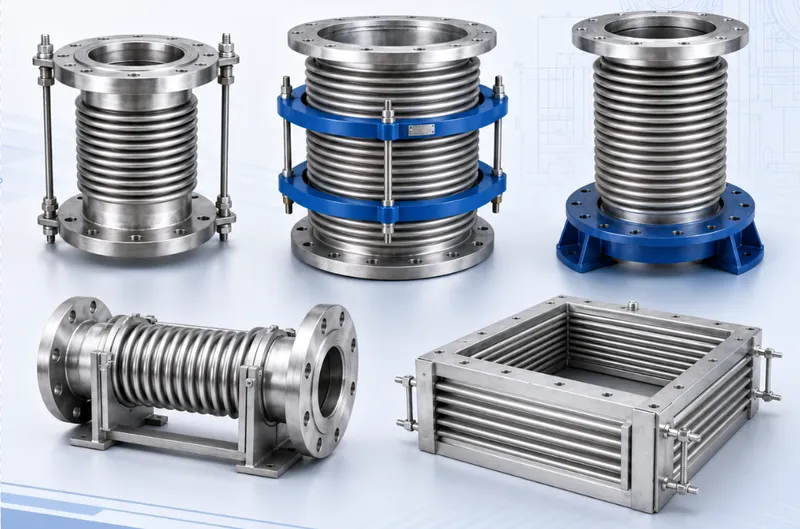
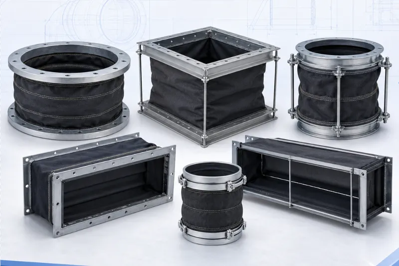
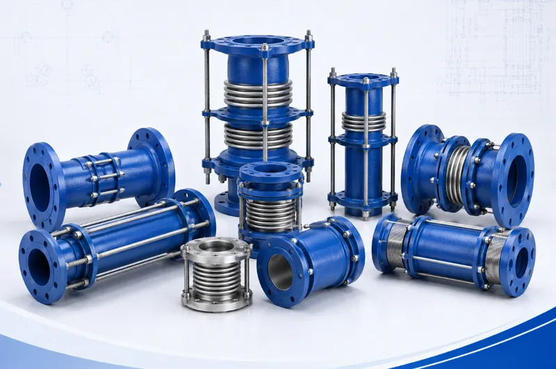
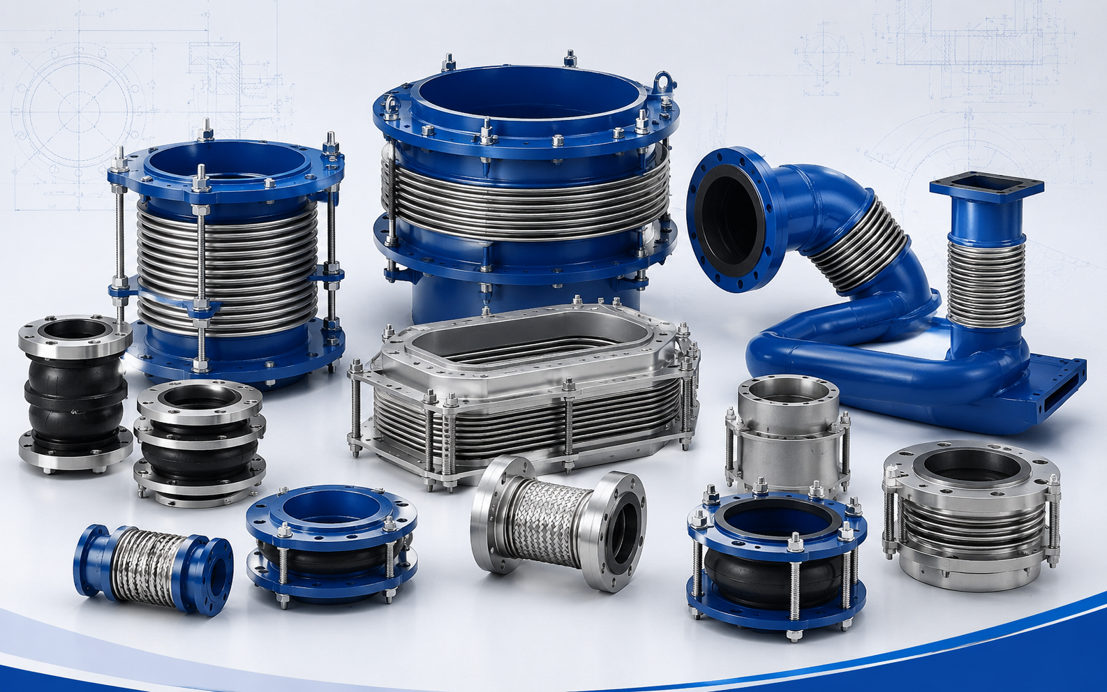

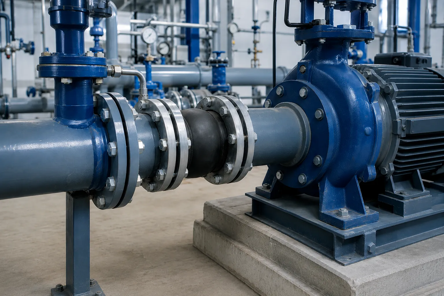
Excessive vibration in pump piping is rarely caused by one component alone. The source may be mechanical, hydraulic, structural or related to the way the piping is supported and connected.
A flexible connector can reduce the transmission of some vibration, but adding one without identifying the root cause may leave pump misalignment, cavitation, pressure pulsation or pipe strain unchanged.
Diagnose the Source Before Changing the Piping
Start by separating the vibration problem into four broad groups: rotating equipment, hydraulic operation, structural response and piping loads.
| Source | Possible Indicators | Initial Review |
|---|---|---|
| Mechanical | High vibration at bearings, pump casing or motor | Alignment, balance, shaft, bearings and coupling |
| Hydraulic | Cavitation noise, unstable pressure or fluctuating flow | Suction flow, air, operating point and valve position |
| Structural | Base, platform or support structure moves with the pump | Foundation, grout, stiffness, anchors and resonance |
| Piping | Pipe movement, flange loosening or support impact | Pipe strain, supports, anchors, guides and pressure thrust |
Collect Operating Data and Establish a Baseline
Record where and when the vibration occurs before replacing a joint or modifying the piping. A baseline makes it possible to compare conditions before and after corrective work.
- Vibration location on the pump, motor, bearing housing, pipe and supports;
- Difference between startup, steady operation and shutdown;
- Change with flow, speed and valve position;
- Suction and discharge pressure behaviour;
- Cavitation, impact, rubbing or pulsation noise;
- Difference between single-pump and parallel operation;
- Visible movement at flanges, anchors and supports;
- Recent equipment or piping changes.
Critical systems should use project-approved instruments and procedures for vibration, pressure, flow and speed measurements.
Check the Pump, Driver and Rotating Assembly
A connector cannot correct vibration generated by a damaged or incorrectly installed pump.
- Pump and driver shaft alignment;
- Coupling condition and assembly;
- Impeller damage, fouling or imbalance;
- Shaft runout or deformation;
- Bearing wear and lubrication;
- Loose baseplate or anchor bolts;
- Internal rubbing between rotating and stationary parts;
- Operation outside the intended pump duty.
Alignment should be reviewed again after piping is connected, because improperly supported pipework may pull the equipment out of alignment.
Review the Pump Suction Piping
Non-uniform inlet flow, entrained air, insufficient submergence and poorly positioned fittings can create unstable hydraulic forces at the pump inlet.
Suction-Side Review
- Pipe size and expected velocity;
- Straight approach to the pump nozzle;
- Location of elbows, valves and reducers;
- High points that may collect air;
- Wet-well or tank liquid level;
- Vortex and air-entrainment risk;
- Blocked strainers or suction lines;
- Minimum internal pressure or vacuum.
A rubber expansion joint installed on suction service must be confirmed for the actual negative-pressure condition. An unsuitable joint may collapse inward and restrict the pump inlet.
Review the Discharge Piping and Valve Dynamics
Discharge-side vibration may be linked to check-valve impact, rapid control-valve movement, pump trips, trapped air or transient pressure.
- Check-valve closing behaviour;
- Control and isolation valve operating position;
- Pump start and stop sequence;
- Pressure pulsation and surge indicators;
- Air pockets and air-release performance;
- Changes during pump sequencing;
- Movement of anchors and supports;
- Unexpected extension of flexible connectors.
Rubber expansion joints are not stand-alone water-hammer devices. Surge requires a system review covering pump controls, valve characteristics, air management and dedicated transient-pressure measures.
Prevent Pipe Strain at the Pump Nozzles
Unsupported or force-fitted piping can apply sustained forces and moments to pump suction and discharge nozzles.
Good Support Practice
- Support pumps, valves, strainers and check valves independently;
- Provide suitable pipe supports near the equipment;
- Do not use a rubber joint to carry suspended pipe weight;
- Align flanges without forcing them together with bolts;
- Use anchors and guides that match the intended movement;
- Prevent support settlement from presetting the flexible connector;
- Review nozzle loading after site piping changes;
- Maintain access for inspection and replacement.
Significant pipe movement after a pump flange is disconnected can indicate stored pipe strain, poor support or geometric misalignment.
Inspect the Foundation, Baseplate and Support Structure
A weak or damaged supporting structure can amplify vibration even when the pump is mechanically sound.
- Foundation cracking or settlement;
- Baseplate distortion or unsupported areas;
- Incomplete or damaged grout;
- Loose or corroded anchor bolts;
- Flexible steel platforms and pipe supports;
- Relative movement between piping and equipment foundations;
- Possible structural resonance;
- Incorrectly adjusted spring or vibration isolators.
When a Rubber Expansion Joint Can Help
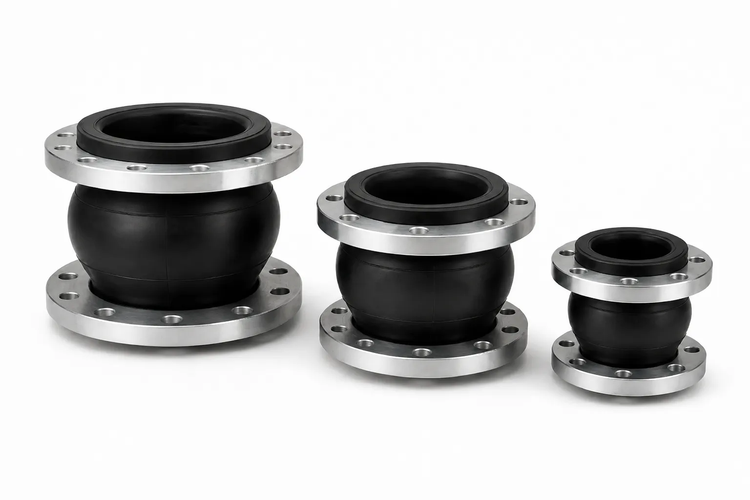
A correctly selected rubber expansion joint can reduce the transmission of some mechanical vibration and structure-borne noise while accommodating limited movement.
It is appropriate to evaluate one when:
- The pump and driver condition has been verified;
- The equipment and pipework are independently supported;
- Vibration or noise transmission needs to be reduced;
- Movement remains within the joint’s approved capability;
- The medium, temperature and pressure are known;
- Vacuum, pressure thrust and restraint have been evaluated.
It should not be used to correct:
- Severe pump or driver misalignment;
- Damaged bearings, shaft or impeller;
- Cavitation and unstable suction flow;
- Loose foundations;
- Severe flange misalignment;
- Missing anchors or pipe supports;
- Water hammer and uncontrolled pressure pulsation;
- Unsupported valve or pipe weight.
Suction and Discharge Joints Need Different Reviews
| Selection Item | Pump Suction | Pump Discharge |
|---|---|---|
| Pressure condition | May operate below atmospheric pressure | Normally positive pressure |
| Primary risk | Inward collapse and flow disturbance | Pressure thrust and overextension |
| Required data | Minimum pressure and vacuum | Operating, design and transient pressure |
| Construction review | Vacuum capability or internal support | Anchors, control rods and pullout protection |
Control Rods, Anchors and Pressure Thrust
Internal pressure across a flexible connector can generate substantial axial thrust. If the piping system does not restrain this force, the joint may extend beyond its allowable movement and transfer loads to the pump or connected equipment.
Control units should be evaluated where:
- Discharge pressure or fluctuation is significant;
- Pipe anchors cannot be verified;
- The joint is close to equipment nozzles;
- Overextension or pullout is possible;
- Allowable nozzle loads are limited;
- The piping is vertical, suspended or difficult to anchor;
- The project specification requires restraint.
Rod quantity, diameter, plate thickness, nut position and movement clearance must follow the approved joint and piping design.
Select the Product for the Actual Function
| Project Requirement | Product Direction | Required Engineering Review |
|---|---|---|
| Reduce vibration transmission | Rubber expansion joint or suitable flexible connector | Pump condition, supports, vacuum and thrust |
| Create valve-removal clearance | Double-flange dismantling joint | Removal direction, support and face-to-face length |
| Connect plain pipe to flanged equipment | Flange adaptor | Actual pipe OD, material and restraint |
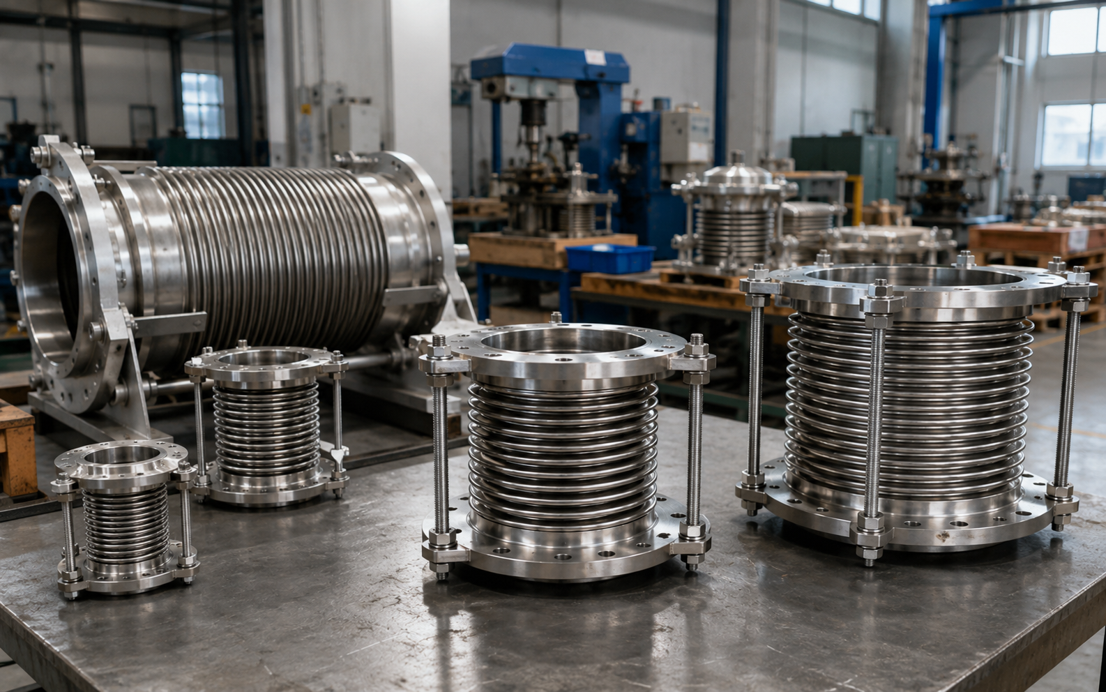
| Accommodate continuous thermal movement | Movement-specific expansion product | Movement, cycles, anchors and guides |
| Control surge or water hammer | System-level surge-control measures | Pump, valve, air and transient analysis |
Installation Checklist for Flexible Pump Connectors
- Verify product type, size, elastomer and service medium;
- Confirm flange standard, drilling and facing;
- Install at the approved neutral face-to-face length;
- Do not stretch, compress or twist the joint to correct major misalignment;
- Support the pump, valves and pipework independently;
- Confirm suction-side vacuum capability;
- Confirm discharge-side pressure thrust and restraint;
- Tighten flange bolts evenly in a cross pattern;
- Prevent bolt or structure contact with the rubber body;
- Maintain movement, inspection and replacement clearance;
- Inspect anchors, guides and control units before operation;
- Depressurize the system before adjustment.
Verify the Result During Operation
Corrective work should be followed by operating checks to confirm that vibration has actually been reduced.
- Compare vibration at the pump, motor, bearings and piping;
- Inspect flange bolts and supports for loosening;
- Check the rubber body for cracking, bulging or distortion;
- Inspect control rods, nuts and plates for movement;
- Check foundations and supports for settlement;
- Observe suction-side cavitation and flow stability;
- Review check-valve impact and discharge pressure fluctuation;
- Confirm that operation remains within the selection basis.
Common Mistakes
- Installing a flexible joint before diagnosing the vibration source;
- Treating pump mechanical failure as a piping problem;
- Ignoring cavitation and air entrainment;
- Allowing pump nozzles to carry pipe and valve weight;
- Forcing misaligned flanges together with bolts;
- Using a rubber joint instead of pipe anchors;
- Ignoring vacuum on pump suction;
- Ignoring pressure thrust on pump discharge;
- Treating the joint as a water-hammer device;
- Removing or reducing control rods;
- Leaving the joint permanently twisted or preset;
- Checking the pump but not the base, supports and pipe strain.
RFQ Information for Pump Piping Connections
- Pump-station type and installation position;
- Pump type, nozzle size and equipment drawing;
- Observed vibration location and operating condition;
- Nominal size and available face-to-face length;
- Medium, composition and solids content;
- Normal, maximum and minimum temperature;
- Operating, design and transient pressure;
- Minimum suction pressure or vacuum;
- Flange, thread or groove standard;
- Axial, lateral and angular movement;
- Anchor, guide and support arrangement;
- Allowable equipment-nozzle loads;
- Control-unit or vacuum-support requirements;
- Elastomer, flange and fastener materials;
- Piping drawings, photographs and vibration records;
- Quantity, documentation, packing and destination.
Request Application-Based Pump Connector Support
For pump stations with excessive piping vibration, flange loosening, abnormal connector movement or equipment-nozzle loading, provide the pump drawing, piping layout, vibration location, medium, pressure, temperature, flange and support information.
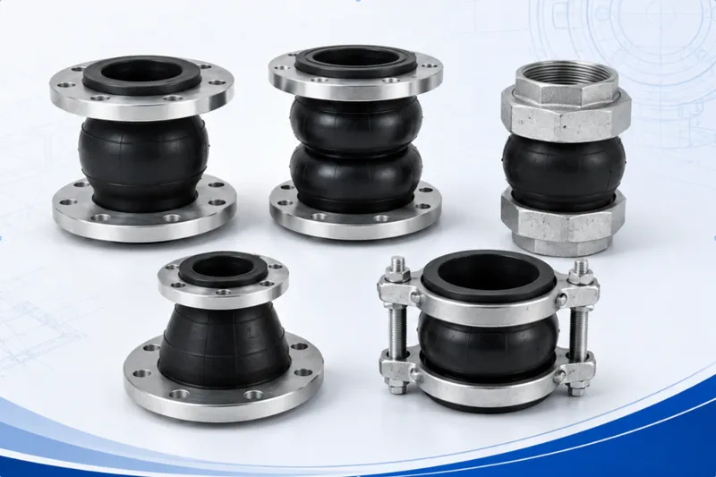
We can assist with evaluating single sphere, double sphere, threaded or grooved rubber expansion joints, together with dismantling joints, flange adaptors and related pipeline connections.
Final construction, dimensions, materials, pressure, vacuum capability, movement, restraint and suitability must follow mutually approved drawings, datasheets, quotations, purchase orders or contracts.