简体中文
简体中文  English
  日本語
日本語  한국어
한국어  Français
  Deutsch
  Español
  Português
  Русский
  العربية
  ไทย
ไทย  Tiếng Việt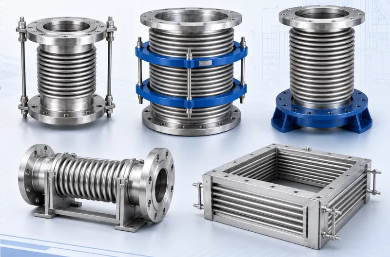

Common Wastewater Plant Piping Problems and How to Reduce Maintenance Risk
Wastewater piping operates under conditions that can change significantly from one process area to another. A single plant may handle raw sewage, screened wastewater, grit-bearing flow, sludge, recycled water, cleaning chemicals, air, odour-control gas and industrial discharges.
The most visible symptom may be a leak or blocked line, but the underlying cause may involve low velocity, settlement, corrosion, an incompatible seal, inadequate supports, transient pressure or poor access for inspection and removal.
Why Wastewater Piping Is More Difficult Than Clean-Water Piping
Wastewater can contain grease, rags, wipes, hair, fibres, grit, biological solids and chemicals. The solids loading and chemical composition may also change during wet weather, industrial discharge or different treatment stages.
These conditions affect the pipe wall, internal coatings, elastomer seals, valves, pumps, instruments and connection hardware. Product selection should therefore be based on the actual process stream, not the general description “wastewater.”
Problem 1: Blockages and Restricted Flow
Hydraulic restrictions can develop when sediment, grease, rags, wipes and other debris accumulate in low-velocity or poorly aligned sections.
Typical Warning Signs
- Increasing upstream level;
- Lower flow at the same pump operating point;
- Higher pressure differential;
- Repeated pump or level alarms;
- Unstable check-valve operation;
- Abnormal noise or intermittent pipe movement;
- Frequent fouling of meters and probes.
Common Contributing Conditions
- Insufficient transport velocity;
- Pipe sags or loss of grade;
- FOG accumulation;
- Fibrous material and wipes;
- Partly closed or obstructed valves;
- Abrupt internal changes in bore;
- Long shutdown periods;
- Insufficient cleaning access.
Increasing pump pressure is not a reliable long-term response. Inspection should determine whether the restriction is caused by deposits, a damaged pipe, an incorrectly positioned valve or structural deformation.
Problem 2: FOG, Sludge and Solids Deposition
Fats, oils and grease can adhere to pipe surfaces and trap fibres, grit and other solids. Sludge lines can also settle rapidly when flow stops or falls below the required transport condition.
High-risk locations include:
- Long horizontal runs;
- Local low points;
- Bends, tees and reducers;
- Valves operating at low opening;
- Sections that cannot be drained or flushed;
- Connections with abrupt internal steps;
- Pump suction lines with poor approach conditions.
Connections for sludge and high-solids service should avoid unnecessary internal pockets and should remain accessible for flushing, inspection or removal.
Problem 3: Infiltration, Inflow and Process Leakage
Cracked gravity sewers, damaged joints and leaking manholes can allow groundwater and stormwater to enter the system, increasing the volume conveyed to lift stations and the treatment plant.
Inside the plant, leakage may occur at flanges, sleeve seals, valve stems, welds, corroded pipe walls and equipment nozzles.
Inspection Points
- Persistent moisture around flanges;
- Leakage at glands and telescopic seals;
- Rust staining or deposits on the pipe exterior;
- Wet ground or settlement above buried lines;
- Abnormal wet-weather flow increase;
- Non-parallel flange faces;
- Uneven bolt loading;
- Seal material incompatible with the process fluid.
Applying more bolt torque may not correct leakage caused by misalignment, a damaged sealing face, an incorrect gasket or excessive pipe loading.
Problem 4: Hydrogen Sulfide and Environmental Corrosion
Anaerobic wastewater conditions can support the formation of sulfur-containing gases. Moisture and corrosive atmospheres may then affect concrete, carbon steel, fasteners, pipe supports, instruments and electrical equipment.
Areas Requiring Particular Attention
- Lift stations and wet wells;
- Force-main discharge locations;
- Sludge storage and processing areas;
- Poorly ventilated valve chambers;
- Gas-liquid interface zones;
- Damaged coating and threaded areas;
- Odour-control ducts with condensation.
Corrosion protection may require coordinated control of material selection, surface preparation, coating, ventilation, process conditions, inspection and repair procedures.
Problem 5: Abrasion from Grit and Suspended Solids
Grit and mineral particles can wear pipe walls, coatings, valve seats and flexible linings, especially at high velocity or where the flow changes direction.
Common inspection areas include:
- The outside radius of bends;
- Pump discharge connections;
- Reducers and tees;
- Valve downstream sections;
- Sludge-transfer piping;
- Locations where coating has already been damaged.
Abrasion resistance depends on particle concentration, velocity, material, geometry and operating time. A higher material grade alone may not correct an unsuitable flow arrangement.
Problem 6: Settlement, Misalignment and Support Failure
Foundation movement, corroded supports, construction tolerances and external loading can shift the pipe centreline or place sustained loads on valves and equipment.
Warning Signs
- Bolts cannot pass freely through mating flanges;
- Flange faces are visibly non-parallel;
- A flexible joint remains twisted or offset;
- A sleeve connection shows uneven gland position;
- Valves and meters are carrying pipe weight;
- Repeated deposits occur at a local sag;
- Supports no longer contact the pipe correctly;
- Equipment foundations and piping have moved differently.
A flexible connector may accommodate limited approved movement, but it should not be used to force severely misaligned piping into position or to support suspended equipment.
Problem 7: Pump Vibration and Nozzle Loading
Vibration may originate from pump misalignment, cavitation, worn components, unsuitable operating points, loose foundations or incorrectly supported piping.
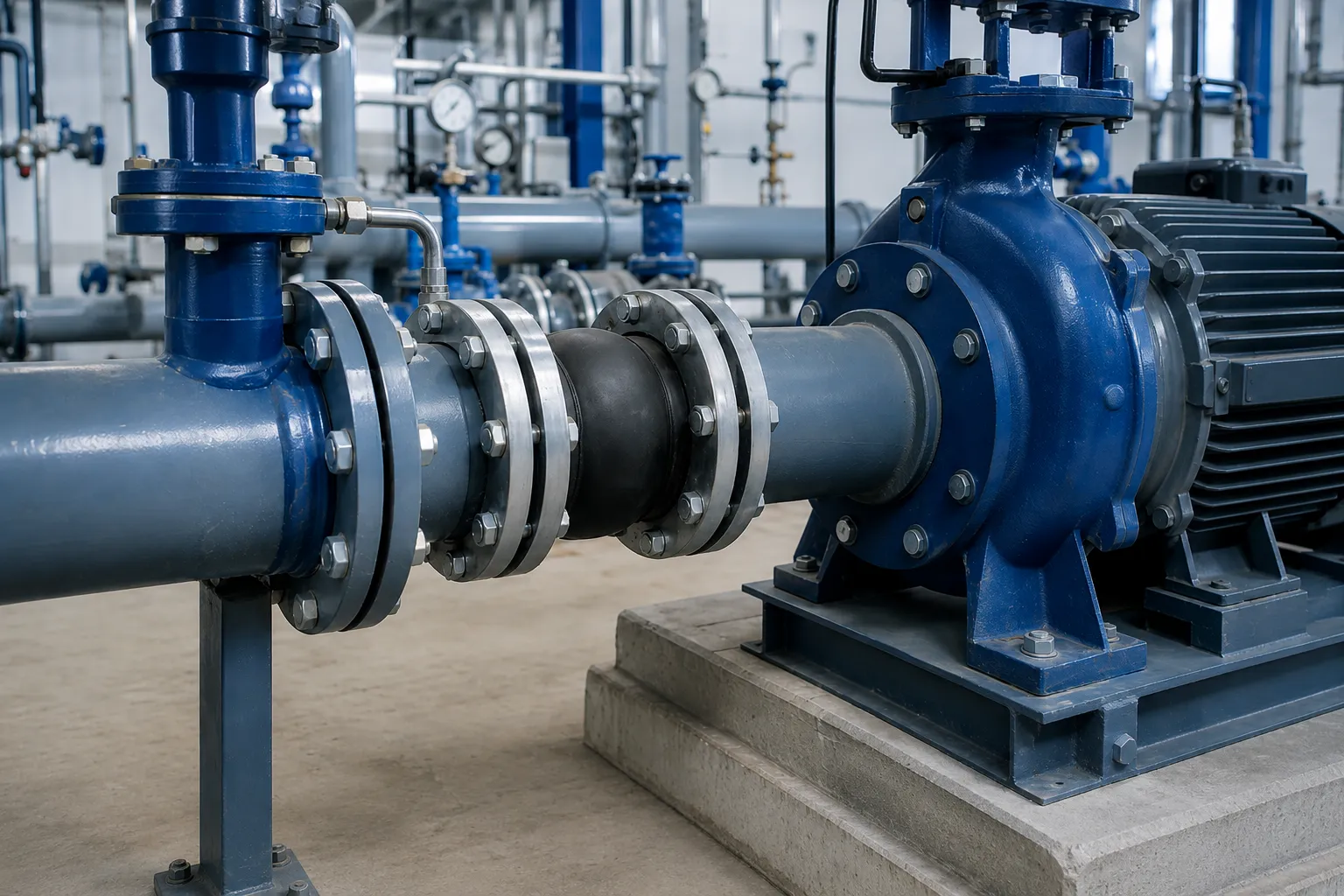
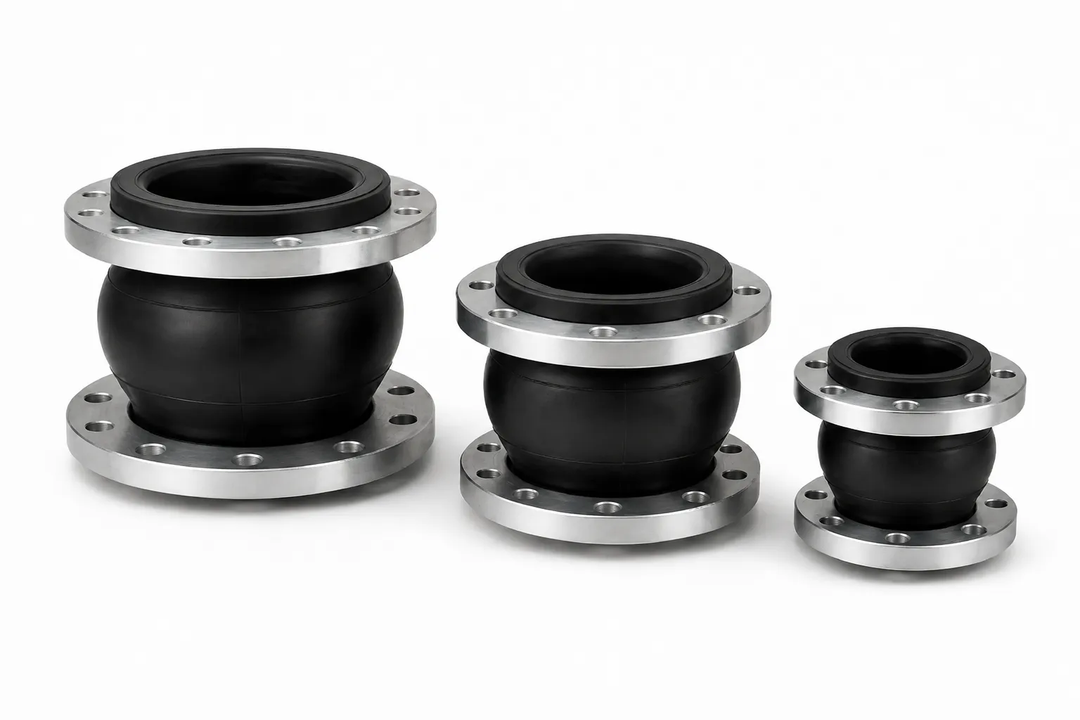
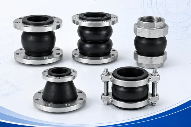
A rubber expansion joint can help reduce the transmission of some mechanical vibration, but it cannot correct a defective pump, unstable hydraulic operation or excessive pipe strain.
Review Before Selecting a Flexible Connector
- Pump and motor alignment;
- Foundation and anchor bolts;
- Independent suction and discharge supports;
- Support for check and isolation valves;
- Neutral installed length of the joint;
- Suction-side vacuum conditions;
- Discharge-side pressure thrust;
- Requirement for control rods or restraint.
Problem 8: Pressure Surges and Check-Valve Slam
Pump trips, rapid valve movement, unstable check-valve closure and moving air pockets can generate transient pressure in force mains and plant pressure piping.
Possible effects include:
- Flange and gasket leakage;
- Overextension of flexible joints;
- Deformed rods, bolts or supports;
- Check-valve impact and noise;
- Movement at pump and equipment nozzles;
- Pipe rupture or connection pullout.
Rubber joints are not stand-alone surge-control devices. Transient pressure should be addressed through pump controls, valve characteristics, air management, surge equipment and hydraulic analysis.
Problem 9: Air and Gas Accumulation
Air and wastewater gases may collect at force-main high points, reducing the effective flow area and contributing to pressure fluctuation, odour and corrosion.
Design and maintenance should confirm:
- Pipeline high points and profile changes;
- Air-release or gas-management locations;
- Suitability for solids-bearing wastewater;
- Risk of fouling by grease and fibres;
- Safe treatment of released gases;
- Access for cleaning and replacement;
- Impact on nearby personnel and equipment.
Problem 10: Incorrect Elastomer and Seal Selection
Wastewater composition varies between municipal, food-processing, oil-containing, chemical and sludge applications.
The material review should include:
- Complete process-fluid description;
- Chemical constituents and concentrations;
- Oil, fuel and solvent content;
- Cleaning and dosing chemicals;
- Normal and maximum temperature;
- Continuous or intermittent exposure;
- Solids and abrasive particles;
- Indoor, outdoor, buried or submerged conditions.
EPDM may be evaluated initially for selected water and wastewater duties, while NBR may be evaluated for selected mineral-oil services. Final suitability remains compound- and application-specific.
Problem 11: Flange and Interface Mismatch
Wastewater projects may include EN, ASME, AWWA, JIS, BS, GB and equipment-specific interfaces. Similar nominal sizes and ratings do not prove compatibility.
Common Procurement Errors
- Providing nominal size without the flange standard;
- Assuming PN16 and Class 150 are interchangeable;
- Ordering a replacement from the old nameplate alone;
- Ignoring flange facing;
- Forcing close but incorrect drilling into position;
- Twisting a rubber joint to align bolt holes;
- Modifying flange holes at site;
- Creating an abrupt internal bore restriction.
Where the standard is unknown, provide the outside diameter, flange thickness, bore, bolt circle, hole quantity and hole diameter, together with the mating-equipment drawing.
Problem 12: No Clearance for Valve and Equipment Removal
Butterfly valves, check valves, flow meters, pumps and strainers may need complete removal. Two fixed pipe sections may not provide enough axial clearance after the flange bolts are removed.
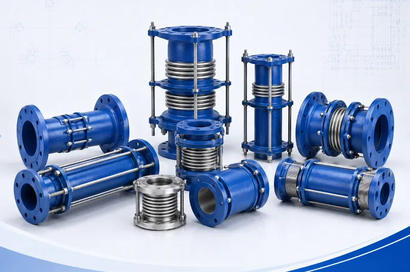
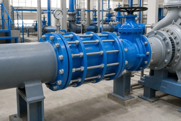
A restrained double-flange dismantling joint can provide installation adjustment and later create removal clearance after shutdown, isolation, drainage and independent equipment support.
Its adjustment range should not be treated as continuous thermal or operational movement.
Matching the Pipeline Product to the Actual Problem
| Project Need | Product Direction | Required Review |
|---|---|---|
| Reduce pump vibration transmission | Rubber expansion joint or suitable flexible connector | Pump condition, supports, vacuum and pressure thrust |
| Create valve-removal clearance | Double-flange dismantling joint | Removal direction, length, supports and tie rods |
| Connect plain pipe to flanged equipment | Flange adaptor | Actual pipe OD, material and tolerance |
| Connect two plain-ended pipes | Steel flexible coupling | Pipe OD, pressure thrust and restraint |
| Accommodate installation tolerance | Suitable telescopic or dismantling connection | Separate installation adjustment from operating movement |
| Accommodate continuous movement | Movement-specific expansion product | Movement, cycles, anchors, guides and thrust |
Build a Preventive Inspection Programme
Wastewater piping should not be managed only through emergency repairs. Inspection frequency should reflect process conditions, failure history and the consequence of shutdown.
Operating Data
- Flow, pressure and level trends;
- Wet-weather influent changes;
- Pump runtime and starts;
- Energy use and transfer efficiency;
- Valve movement and check-valve impact;
- Alarm and overflow history.
Physical Inspection
- Flange, gland and valve-stem leakage;
- Pipe, support and equipment movement;
- Coating damage and corrosion;
- Cracking or deformation of rubber joints;
- Corrosion of rods, bolts and nuts;
- Abnormal vibration and noise;
- Condition of air valves, drains and cleaning points;
- Availability of lifting and maintenance access.
RFQ Information for Wastewater Pipeline Products
- Process area and installation position;
- Gravity, force-main, sludge or process piping;
- Nominal size and actual pipe outside diameter;
- Medium, solids content and chemical composition;
- Oil, fuel, solvent and cleaning-agent content;
- Normal, maximum and minimum temperature;
- Operating, design and test pressure;
- Possible vacuum or negative pressure;
- Flange, groove, thread or plain-pipe interface;
- Required face-to-face length;
- Axial, lateral and angular movement;
- Anchors, guides and equipment supports;
- Transient-pressure information where available;
- Body, elastomer, seal and fastener materials;
- Coating and corrosion conditions;
- Drawings, photographs, quantity and documents.
Request Application-Based Pipeline Connection Support
For wastewater treatment plants, lift stations, sludge systems, pumps, valves and meter connections, provide the process medium, pressure, temperature, pipe dimensions, interface standard and maintenance requirements.
We can assist with evaluating rubber expansion joints, double-flange dismantling joints, pipe expansion joints, flange adaptors, steel flexible couplings and related pipeline connection products.
Final construction, dimensions, materials, pressure conditions, movement capability, documentation and supply scope must follow mutually approved drawings, datasheets, quotations, purchase orders or contracts.