简体中文
简体中文  English
  日本語
日本語  한국어
한국어  Français
  Deutsch
  Español
  Português
  Русский
  العربية
  ไทย
ไทย  Tiếng Việt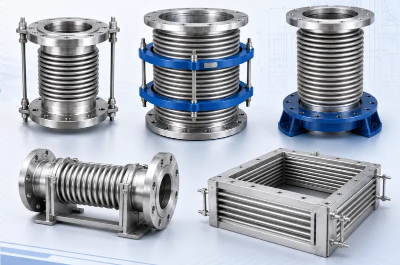
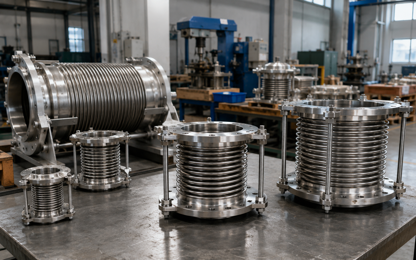
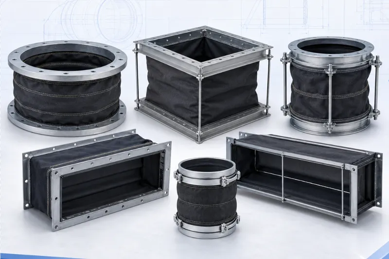
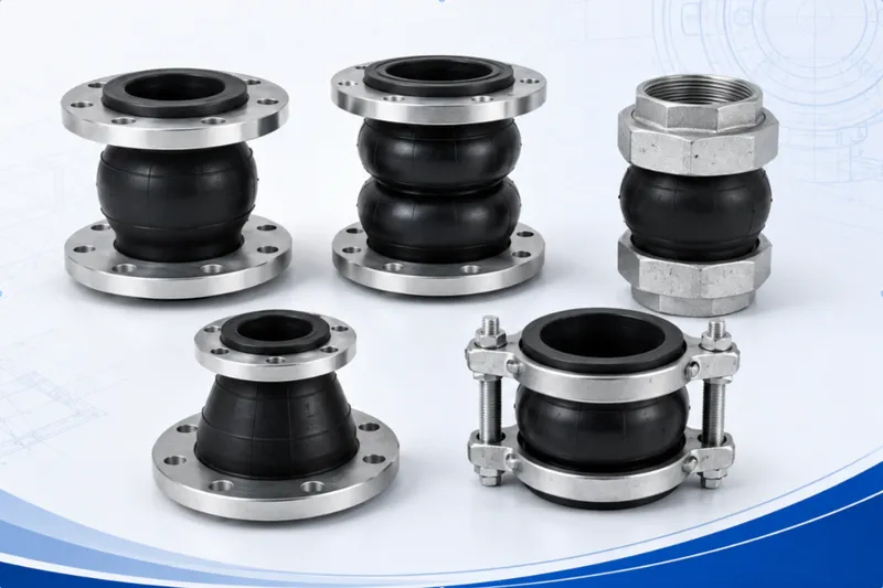
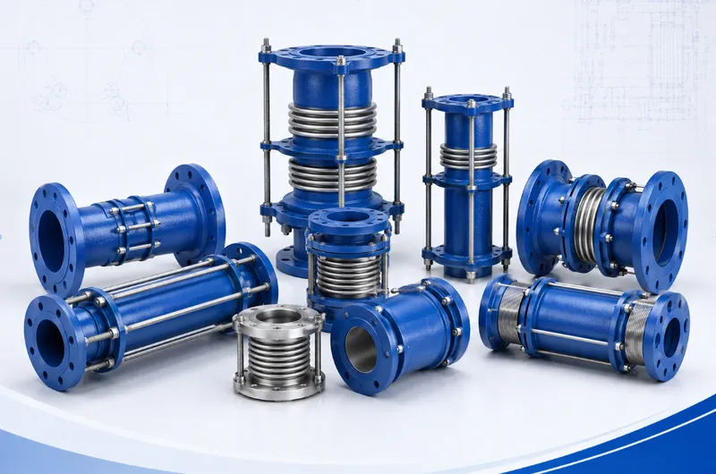
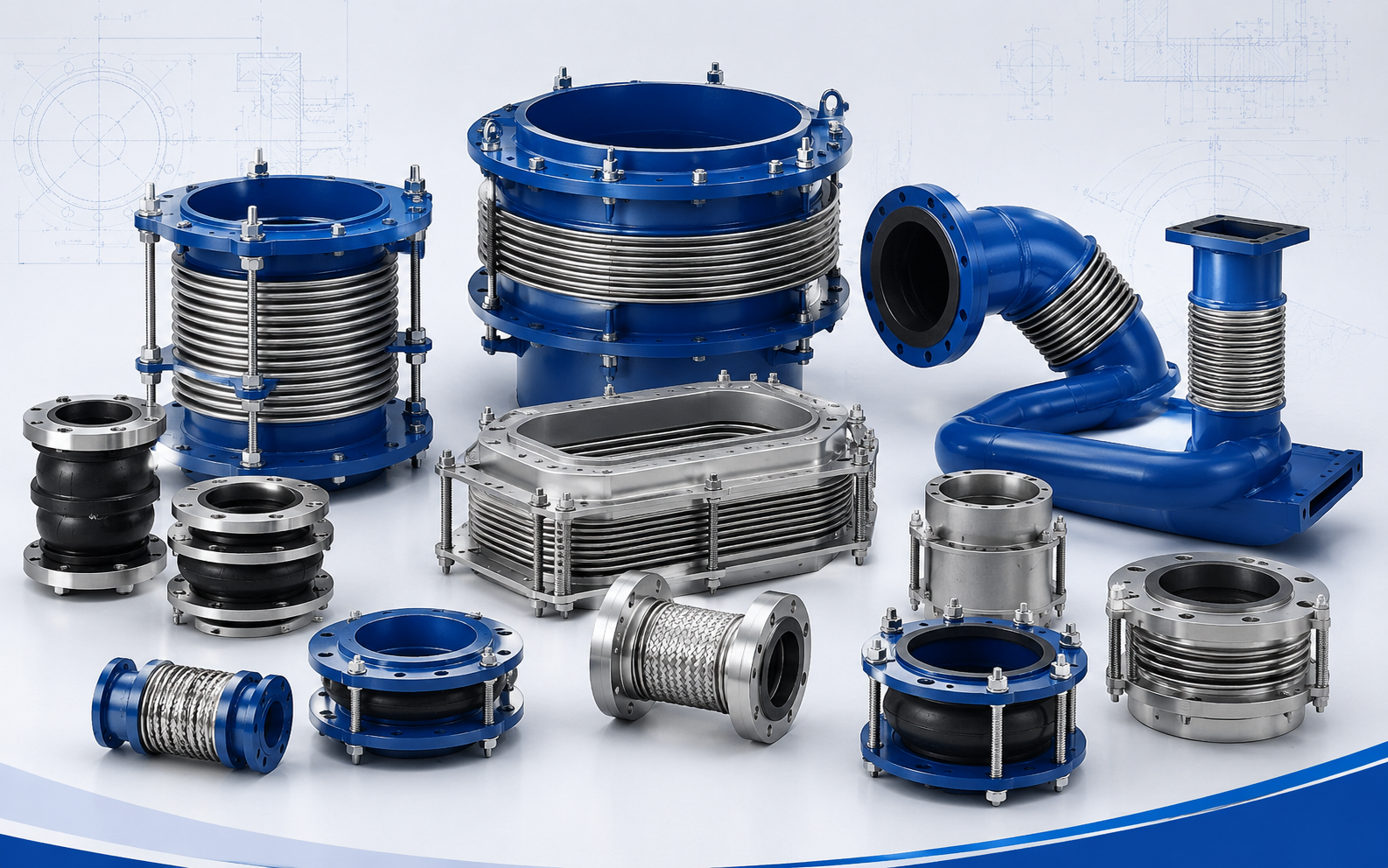

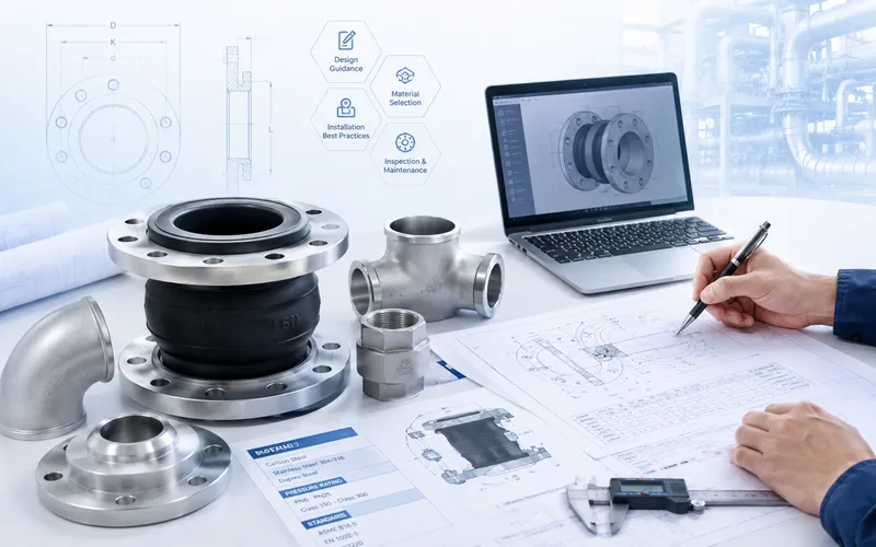
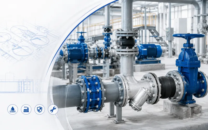
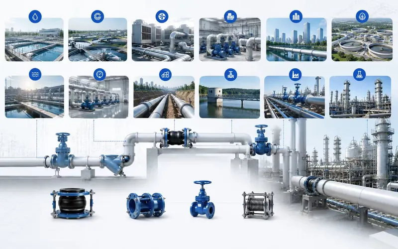
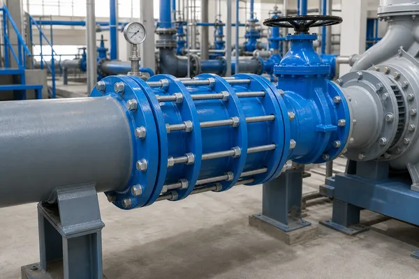
This reference case study considers a typical water treatment facility with raw-water pumping, process equipment, filtration, backwash piping, clear-water pumping and flanged valve assemblies.
It is not presented as a verified customer project. No actual plant name, location, treatment capacity, pipe size, pressure, quantity or measured operating result is claimed.
Reference Project Scope
A water treatment plant may contain several piping environments even when water is the principal medium. Pump suction, pump discharge, chemical dosing, filter backwash and treated-water distribution can have different pressure, corrosion and maintenance conditions.
This reference arrangement includes:
- Raw-water and treated-water pump connections;
- Isolation and check-valve assemblies;
- Flow-meter and filter equipment interfaces;
- Plain-ended pipe connected to flanged equipment;
- Building and tank wall penetrations;
- Pipeline sections requiring planned maintenance access.
Key Design Challenges
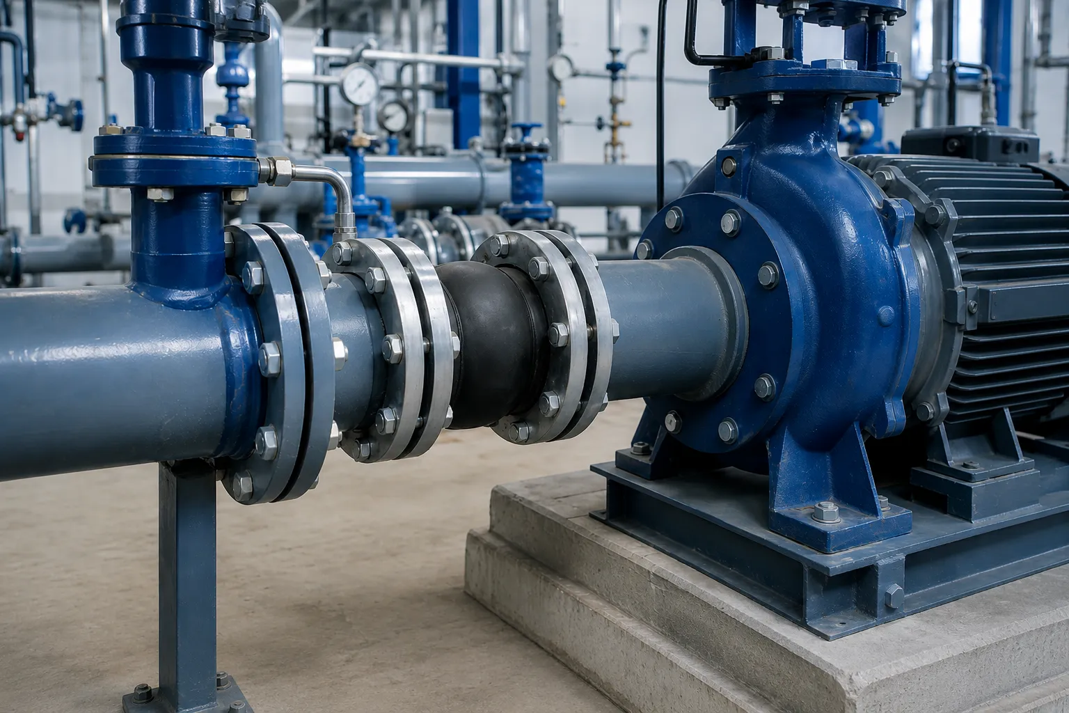
Separating Pump Vibration from Pipe Loads
Pumps may transmit mechanical vibration to the connected piping, but pipe weight and forced alignment can also load the pump nozzles. The piping, valves and other heavy equipment therefore require independent support.
Providing Valve-Removal Clearance
A butterfly valve, check valve or meter installed between two fixed flanges may be difficult to remove even after all flange bolts have been released.
Managing Mixed Pipe Interfaces
Treatment-plant upgrades may connect new flanged equipment to existing steel, ductile-iron or other plain-ended pipelines. Nominal size alone does not define the actual pipe outside diameter.
Controlling Corrosion and Moisture Exposure
Condensation, outdoor exposure, buried chambers, treatment chemicals and continuously wet areas can affect bodies, coatings, rods, bolts and elastomer seals.
Maintaining Access Over the Plant Lifecycle
Pumps, valves, meters and filters may require inspection or replacement before the surrounding pipeline is renewed. Removal access should therefore be planned during design.
Connection Strategy by Plant Area
| Plant Location | Product Direction | Primary Function | Required Review |
|---|---|---|---|
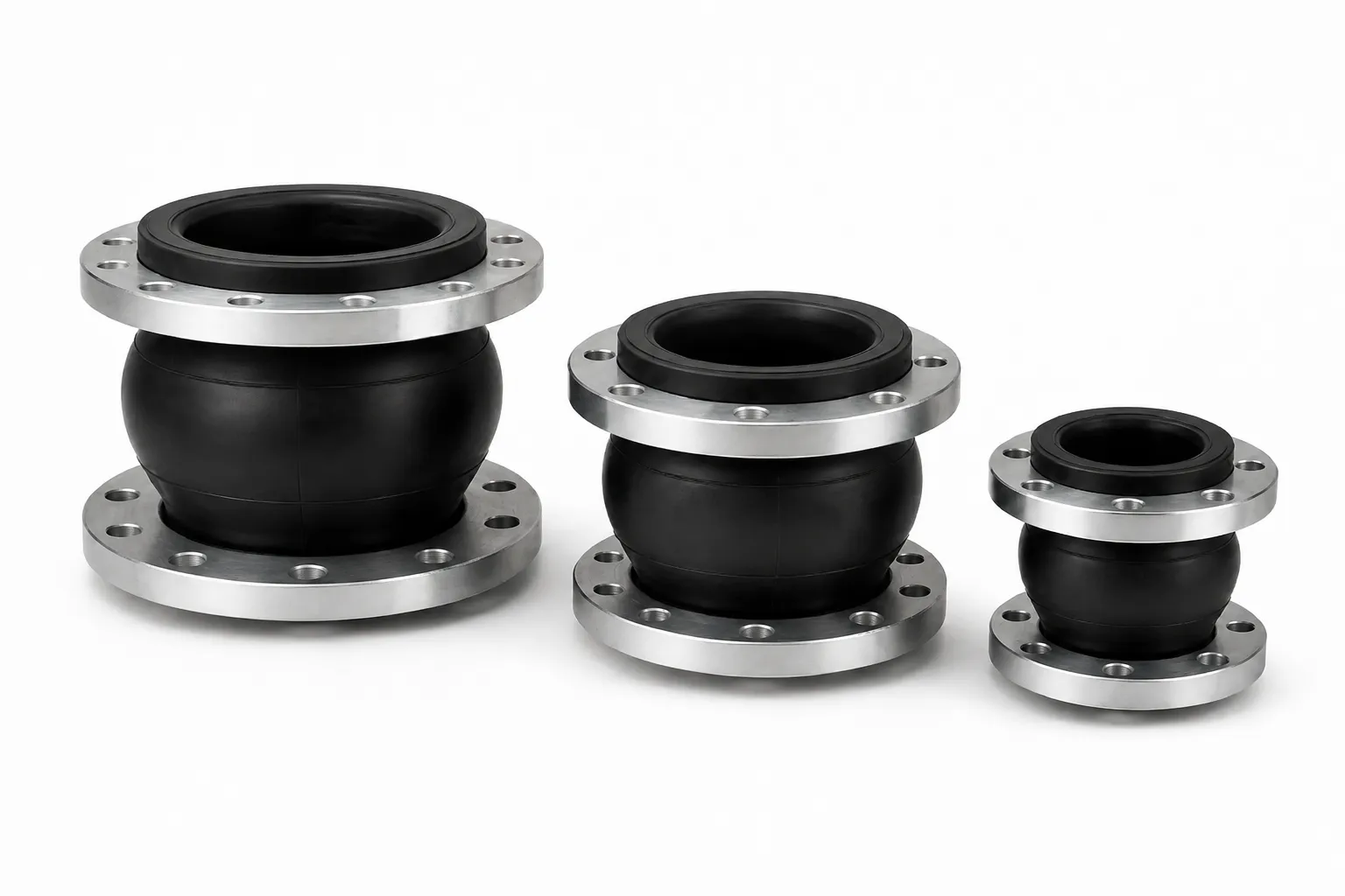
| Pump suction or discharge | Rubber expansion joint | Flexible connection and reduced vibration transmission | Vacuum, pressure thrust, support and restraint |
| Beside valves and meters | Double-flange dismantling joint | Installation adjustment and removal clearance | Face-to-face length, removal direction and tie rods |
| Plain pipe to flanged equipment | Flange adaptor | Transition between plain pipe and flange | Actual pipe OD, material and sealing range |
| Plain pipe to plain pipe | Steel flexible coupling | Join plain-ended pipe sections | Pipe OD, thrust and pullout restraint |
| Controlled length adjustment | Suitable telescopic expansion joint | Approved installation adjustment | Installation tolerance versus operating movement |
| Wall or tank penetration | Rigid or flexible waterproof sleeve | Locate and seal the structural penetration | Wall thickness, pipe OD and structural movement |
Pump-Room Connection Arrangement
Suction-Side Review
Pump suction may operate below atmospheric pressure. A rubber expansion joint should therefore be checked against the actual minimum internal pressure and any requirement for vacuum support.
The layout should also confirm:
- Stable inlet-flow conditions;
- No avoidable air pocket at the pump inlet;
- Independent pipe and valve supports;
- Neutral installed length of the joint;
- No inward deformation that restricts the flow path.
Discharge-Side Review
Pump discharge normally operates under positive pressure. Internal pressure across a flexible joint can produce axial thrust, so anchors and control units must be evaluated.
A rubber joint should not be used as a replacement for pump repair, pipe anchors or dedicated surge-control equipment.
Support of Heavy Valves
Check valves, isolation valves and strainers should not be suspended from the rubber joint or supported by the pump nozzle.
Maintainable Valve and Meter Assemblies
A restrained double-flange dismantling joint can be placed beside selected valves, meters and other flanged equipment that must be removed during plant maintenance.
The telescopic section provides controlled installation adjustment. After the flanges, gland and tie rods have been secured, the joint forms a restrained connection.
During maintenance, the isolated and depressurized assembly may be shortened according to its design to create equipment-removal clearance.
Layout Questions
- Which direction must the valve or meter be removed?
- Is lifting equipment available?
- Should the joint be upstream or downstream?
- How much removal clearance is required?
- Are the gland and tie rods accessible?
- Will the remaining pipe stay independently supported?
The installation adjustment of a dismantling joint should not be treated as continuous thermal movement.
Filter, Backwash and Process Equipment Connections
Filters, backwash pumps, valve manifolds and process equipment may need periodic cleaning or replacement. Their pipeline connections should be designed around both hydraulic performance and maintenance access.
- Avoid unnecessary internal steps in solids-bearing service;
- Support filters and valves independently;
- Provide clearance for screens and internal components;
- Review changing backwash pressure conditions;
- Confirm seal compatibility with cleaning chemicals;
- Provide drainage, flushing and inspection access.
Chemical dosing and special process-water lines require the full chemical name, concentration and temperature before the seal material is selected.
Connecting Plain-Ended Pipe to Flanged Equipment
A flange adaptor can connect a plain-ended pipe to a flanged valve, pump or process item. The flange end must match the equipment, while the sealing end must match the actual pipe outside diameter.
Required Pipe Information
- Measured outside diameter;
- Pipe material;
- Outside-diameter tolerance;
- Pipe-end roundness and surface condition;
- Flange standard and rating;
- Operating pressure and axial thrust;
- Requirement for pullout restraint.
A nominal DN or NPS designation alone may not be sufficient to select the sealing range.
Wall Penetration Details
Pipework passing through tanks, basements, treatment buildings and underground structures may require a rigid or flexible waterproof sleeve.
The civil and piping drawings should identify:
- Pipe outside diameter;
- Wall or tank thickness;
- Expected relative movement;
- Internal and external water conditions;
- Elevation and installation direction;
- Cast-in or other installation method;
- Sealing and corrosion requirements;
- Structural penetration detail.
A waterproof sleeve addresses the structural penetration. It does not replace expansion compensation, pipe anchors or a flexible equipment connection.
Materials and Corrosion Protection
Elastomers and Seals
Water-compatible compounds may be evaluated for clean-water and general circulation duties. Oil, cleaning chemicals and treatment additives may require another compound.
A base polymer name alone does not prove compliance with potable-water project requirements.
Metallic Components
Body, gland, sleeve and flange materials should be selected from pressure, fabrication, pipe material and corrosion conditions.
Coating and Fastener Protection
- Specify internal and external coating systems;
- Define surface preparation and coating inspection;
- Review outdoor, buried and humid exposure;
- Protect tie rods, nuts, washers and threaded areas;
- Define repair of site coating damage;
- Review corrosion between dissimilar metals.
Flange and Dimensional Control
EN, ASME, AWWA, JIS, BS, GB and equipment-specific flange interfaces may be present in one water treatment project.
The manufacturing information should include:
- Complete flange standard;
- DN, NPS or other nominal size;
- PN, Class, K or another rating;
- Flange facing;
- Outside diameter and thickness;
- Bolt-circle diameter;
- Bolt-hole quantity and diameter;
- Mating equipment drawing;
- Gasket and bolting requirements.
Existing plants should be measured before replacement products are manufactured.
Recommended Installation Sequence
- Confirm the approved product, drawing and installation position;
- Inspect flanges, coatings, seals and fasteners;
- Complete independent pipe, valve and equipment supports;
- Measure the actual installation gap and flange alignment;
- Adjust the connection within its approved range;
- Tighten flanges, glands and tie rods evenly;
- Check for twisting, eccentricity and unintended preset;
- Verify anchors, guides and equipment nozzle loads;
- Flush, vent and test according to the project procedure;
- Inspect leakage, movement and vibration after commissioning.
Do not release flange, gland, control-unit or tie-rod connections while the pipeline is pressurized.
Inspection and Documentation Package
Inspection and document requirements should be agreed before production.
Possible Inspection Scope
- Appearance and quantity;
- Critical dimensions and face-to-face length;
- Flange drilling and sealing surfaces;
- Welding and assembly condition;
- Seal and fastener configuration;
- Coating condition and specified checks;
- Pressure or sealing test where ordered;
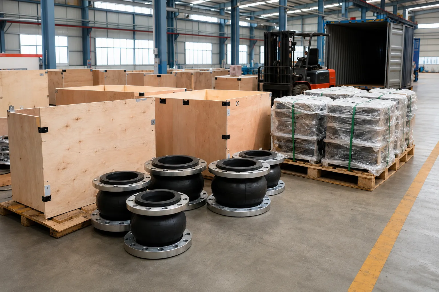
- Marking and export packaging.
Possible Project Documents
- Approved manufacturing drawing;
- Product datasheet;
- Dimensional inspection record;
- Material or coating documentation;
- Test and inspection records;
- Packing list;
- Installation and maintenance instructions.
Procurement Mistakes to Avoid
- Presenting a reference layout as an unverified completed project;
- Selecting every product from DN and PN alone;
- Using rubber joints as a universal solution;
- Treating dismantling adjustment as continuous movement;
- Allowing connectors to carry valve or pipe weight;
- Ignoring suction-side vacuum;
- Ignoring discharge-side pressure thrust;
- Ordering replacement fittings without measuring the interface;
- Protecting the body but not rods and fasteners;
- Assuming a polymer name proves potable-water compliance;
- Adding inspection requirements after production;
- Providing no clearance for valve or meter removal.
RFQ Checklist for a Water Treatment Piping Package
- Plant type and process area;
- Installation location and required function;
- Piping and equipment drawings;
- Nominal size and actual pipe outside diameter;
- Required face-to-face length;
- Medium, composition and solids content;
- Normal, maximum and minimum temperature;
- Operating, design, test and vacuum conditions;
- Flange, groove, thread or plain-pipe interface;
- Axial, lateral and angular movement;
- Installation adjustment or operating movement;
- Anchors, guides and equipment supports;
- Body, flange, elastomer, seal and fastener materials;
- Coating and potable-water requirements;
- Inspection and documentation requirements;
- Quantity, packing and destination.
Request a Project-Based Connection Review
For raw-water pumping, clear-water pumping, filtration, backwash, valve chambers, meters and structural penetrations, provide the piping drawings, equipment interfaces, medium, temperature, pressure and maintenance requirements.
We can assist with evaluating rubber expansion joints, double-flange dismantling joints, expansion joints, flange adaptors, steel flexible couplings, waterproof sleeves and related valve products.
Final construction, dimensions, materials, pressure, movement, flange interfaces, documentation and supply scope must follow mutually approved drawings, datasheets, quotations, purchase orders or contracts.