简体中文
简体中文  English
  日本語
日本語  한국어
한국어  Français
  Deutsch
  Español
  Português
  Русский
  العربية
  ไทย
ไทย  Tiếng Việt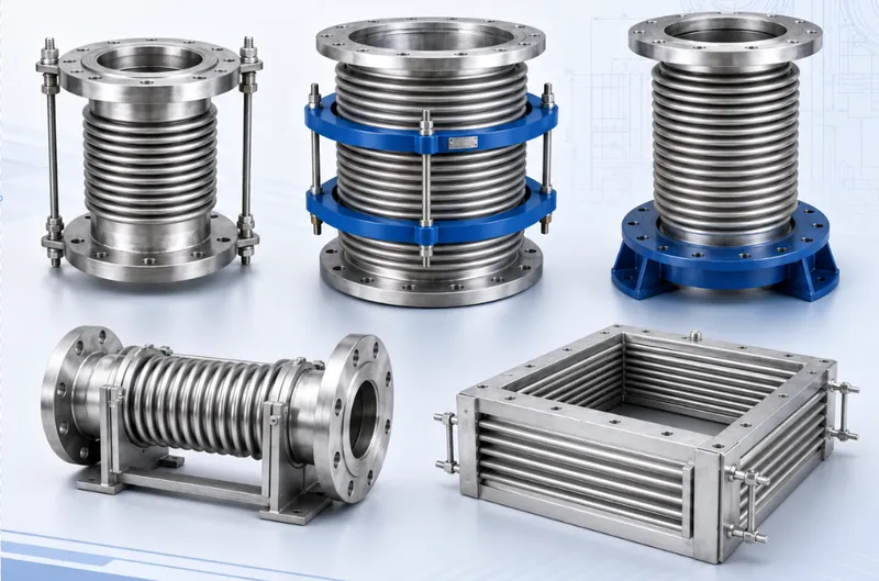
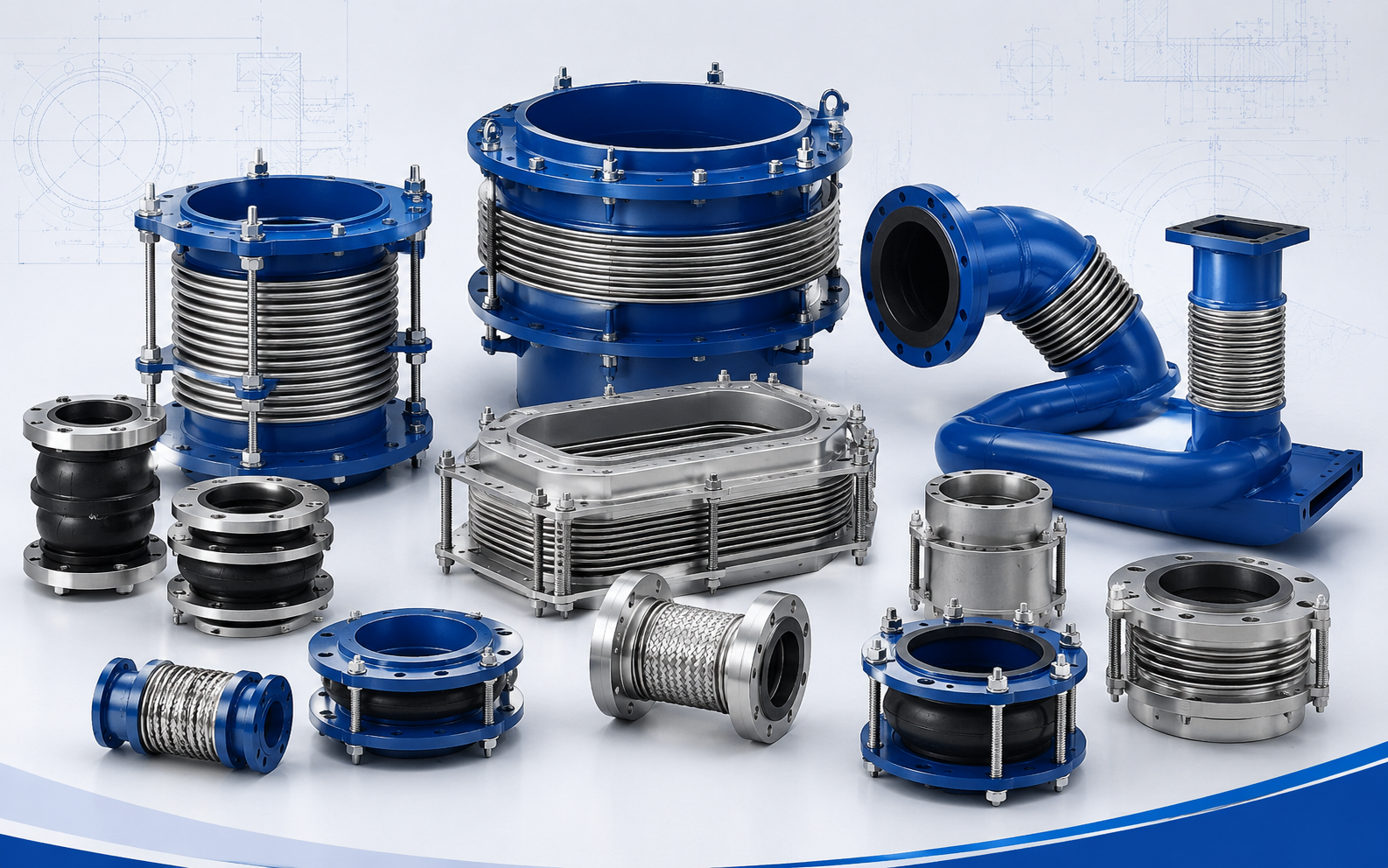

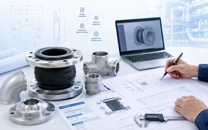


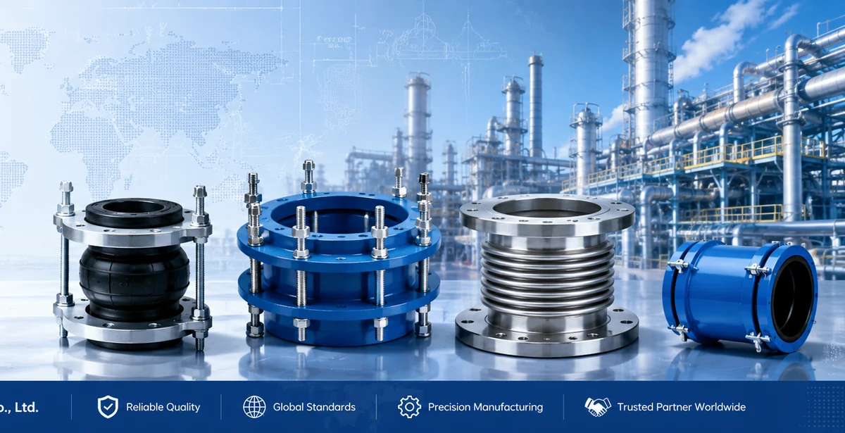
Visual Guide to Pipeline Connection and Expansion Products
Pipeline connection and movement-control products may look similar, but their internal structures, load-transfer characteristics and intended applications can be very different. Selecting the wrong product may result in incorrect installation length, uncontrolled pipeline thrust, vibration transmission or difficulties during equipment maintenance.
This guide focuses on products used for flexible connection, vibration isolation, equipment dismantling, axial movement, thermal expansion and pipeline force transmission. Conventional welded fittings such as elbows, tees and reducers are not the primary subject of this guide.
1. How to Identify Pipeline Connection Products
Four visual and functional characteristics should be checked first:
- Connection type: flanged, threaded, grooved, gland-type or welded.
- Main structure: rubber sphere, steel sleeve, metallic bellows, fabric body or rigid flange assembly.
- Movement direction: axial, lateral, angular or combined movement.
- Load control: whether the product includes tie rods, limit rods, restraint devices or force-transmission components.
Use rubber joints where vibration isolation is important. Consider dismantling or expansion joints where installation adjustment and equipment removal are required. For thermal movement, select a metallic or non-metallic compensator according to the medium, temperature and movement direction.
2. Rubber Expansion Joints
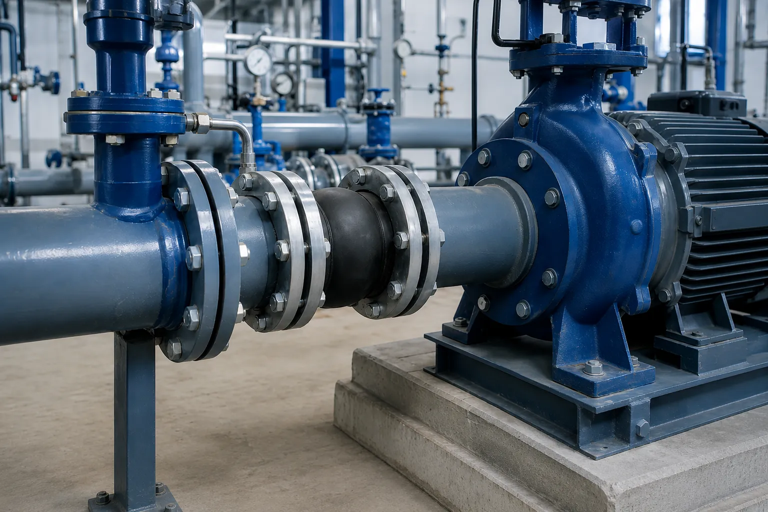
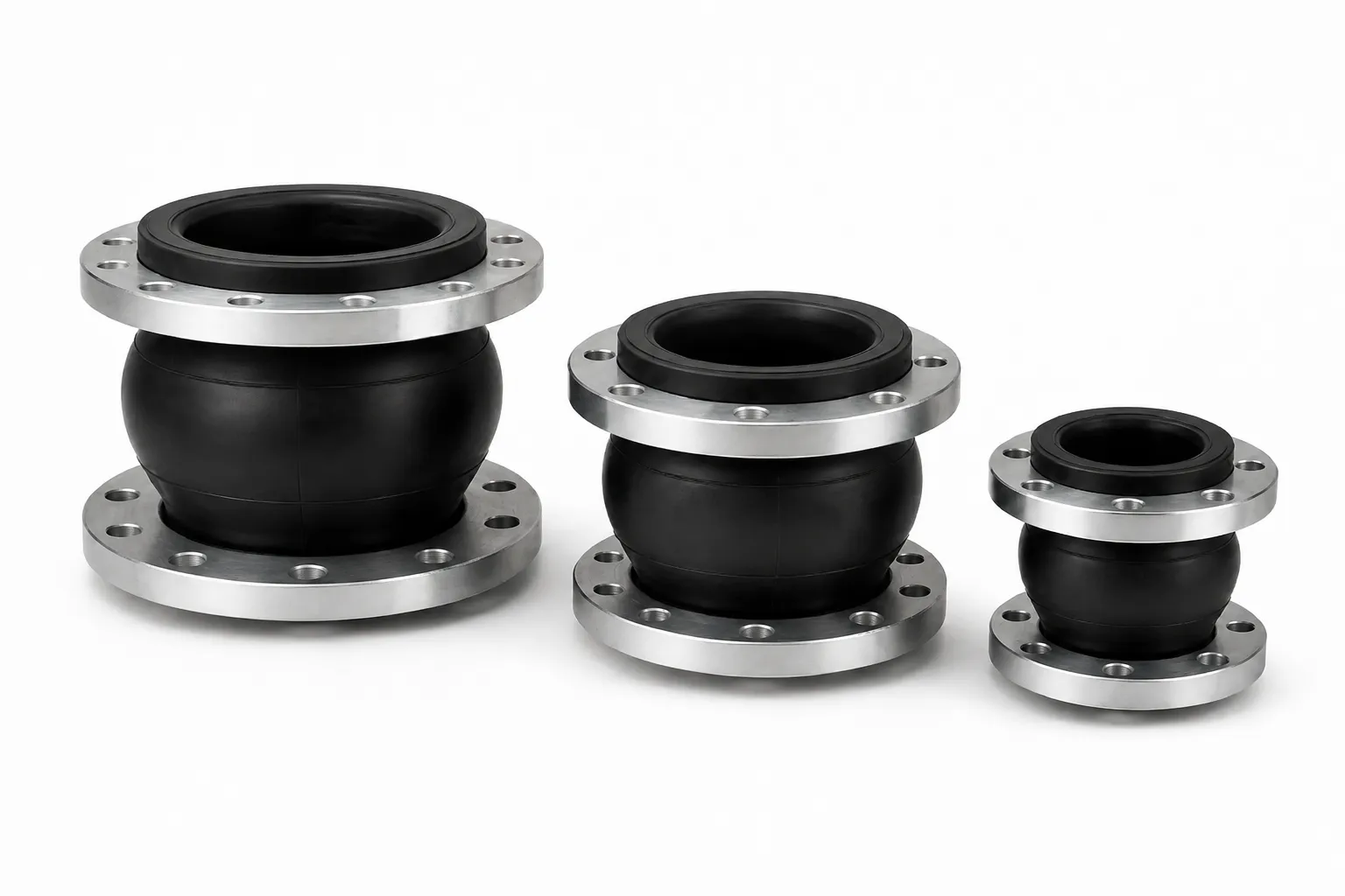
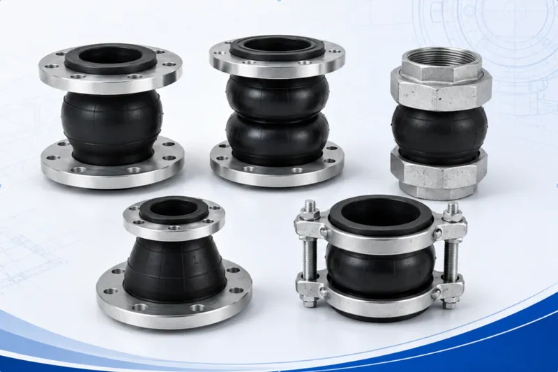
Rubber expansion joints normally consist of an elastomer body, reinforcing fabric layers and end connections. Their most recognizable feature is the raised rubber sphere positioned between the two pipe connections. They are commonly used for vibration isolation, noise reduction and limited axial, lateral and angular movement.
Single Sphere Rubber Expansion Joint
The single-sphere design is compact and widely used near pumps, valves, circulation systems, water-treatment equipment and general industrial piping. The medium, temperature, pressure, flange standard and actual movement requirements must be confirmed before selection.
Double Sphere Rubber Expansion Joint
A double-sphere joint has two connected rubber arches and a visibly more flexible body. Its installation length and stability should be evaluated together with the pipeline layout and restraint conditions.
Threaded Rubber Expansion Joint
Threaded rubber joints are mainly used in smaller pipe connections and auxiliary systems. The thread standard, male or female connection and metallic end material should be specified during inquiry.
Grooved Rubber Flexible Coupling
Grooved rubber flexible couplings use grooved or clamp-type end connections rather than conventional flanges. They are suitable for grooved piping systems where convenient installation and dismantling are required.
Rubber Duct Expansion Joint
Rubber duct compensators are generally designed for air, gas or low-pressure ducting systems. Their cross-sectional shape, dimensions and connection frames can be customized according to the duct design.
3. Dismantling and Force-Transmission Joints
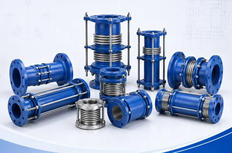
Dismantling and force-transmission joints normally contain a steel body, flanges, sealing components and connecting bolts. They provide installation adjustment and can transfer axial forces through their structural components.
Single Flange Force-Transmission Joint
A single-flange design normally has one flanged end and one end intended for welding to the pipe. It can be recognized by its single flange, steel sleeve and longitudinal fastening components.
Double Flange Dismantling Joint
A double-flange dismantling joint is commonly installed next to pumps, valves and other flanged equipment. It provides adjustable installation space and simplifies future equipment removal. Installation length, flange standard and pipeline thrust must be confirmed.
4. Pipe Expansion Joints and Sleeve-Type Connectors
Pipe expansion joints use sleeves, sealing rings, glands, flanges or limit devices to provide controlled axial adjustment. They are frequently used in water pipelines, pumping stations, valve installations and long-distance transmission systems.
Single Flange Limit Expansion Joint
This product normally has one flanged end and one welding end. Limit rods or similar restraint components control the permitted extension range and help prevent excessive movement.
Double Flange Limit Expansion Joint
Both ends are flanged, making the product suitable for installation between flanged pipes, valves or equipment. Typical visual features include two flanges, a central sleeve and multiple longitudinal limit rods.
Flanged Loose Sleeve Expansion Joint
A flanged loose-sleeve design provides axial installation adjustment through a sliding sleeve and sealing arrangement. External supports and pipeline thrust restraint must be determined by the system designer.
Gland-Type Loose Sleeve Expansion Joint
This design uses a gland to compress the sealing ring around the sleeve. It can be identified by the relationship between the gland, sealing chamber and sliding pipe section.
Sleeve Expansion Joint
A typical sleeve expansion joint has a compact cylindrical body, upper and lower flange plates, a central sleeve and vertical tie rods or bolts. It should not be confused with long-body flanged products using horizontal tie rods.
5. Flange Adaptors and Steel Flexible Couplings
Flange Adaptor
A flange adaptor connects a plain-ended pipe to a flanged valve, fitting or item of equipment. One end normally has a standard flange, while the other uses a gland and sealing ring to grip the pipe.
Steel Flexible Pipe Coupling
A steel flexible coupling connects two plain-ended pipes and can accommodate a limited range of pipe outside diameters and installation misalignment. The actual pipe outside diameter must be confirmed rather than providing nominal size alone.
6. Metallic Bellows Expansion Joints
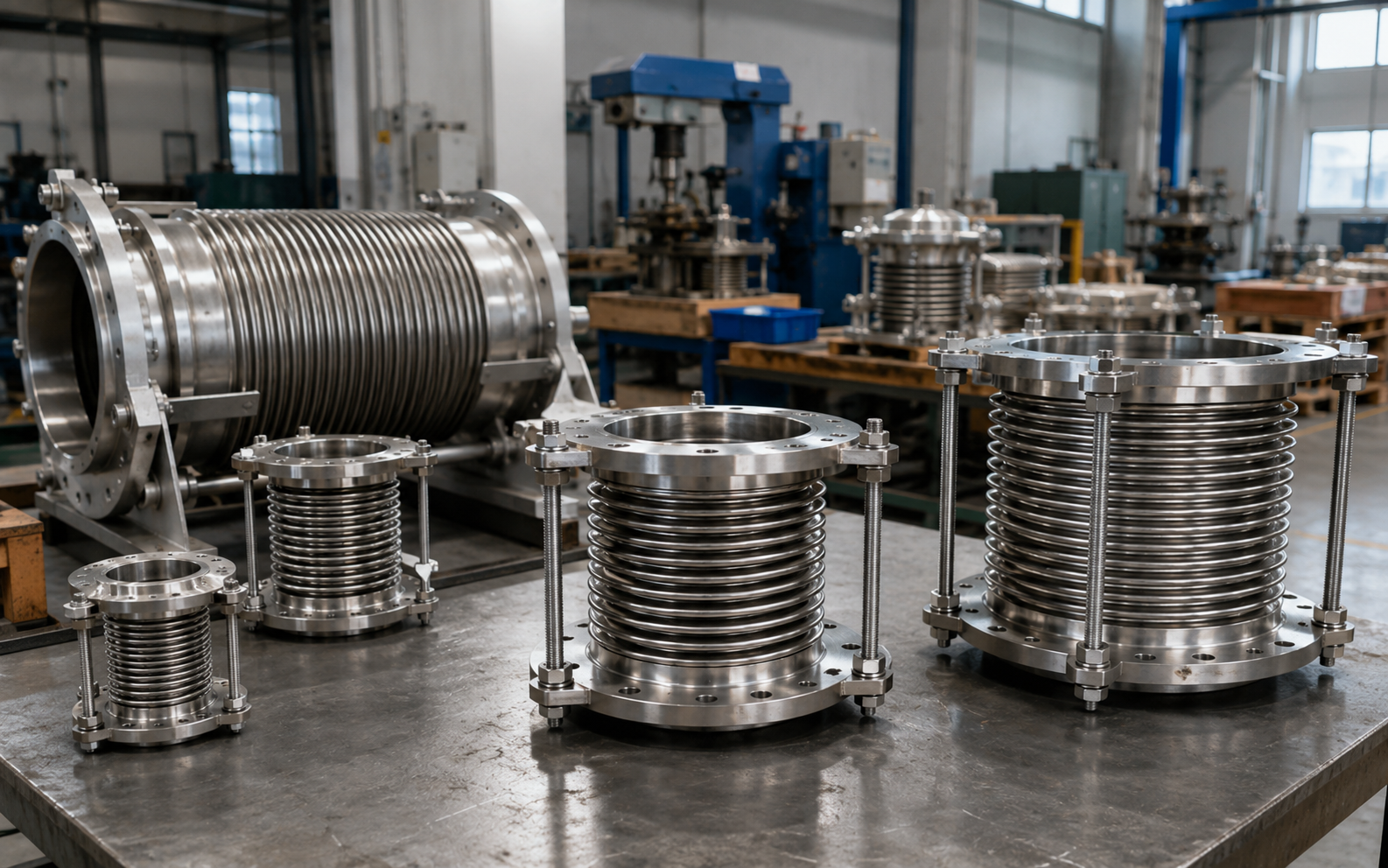
The key component of a metallic expansion joint is the metal bellows. Elastic deformation of the bellows absorbs thermal movement, mechanical displacement or equipment-induced movement. Each design is intended for specific movement directions and load conditions.
Axial Internally Pressurized Bellows Expansion Joint
This design primarily absorbs movement along the pipeline axis. Main anchors, intermediate anchors and guide supports must be considered as part of the complete piping design.
Direct-Buried Bellows Expansion Joint
Direct-buried expansion joints are designed for underground pipeline conditions and often include protective external sleeves. Burial conditions, corrosion protection, pipeline routing and construction requirements should be confirmed during selection.
7. Non-Metallic Expansion Joints
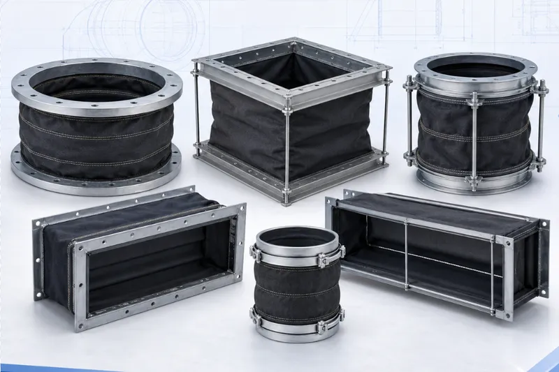
Non-metallic expansion joints normally consist of flexible fabric layers, insulation materials, a metallic frame and connecting flanges. They are particularly suitable for ducts requiring combined movement and large cross-sectional dimensions.
Selection should consider gas temperature, chemical composition, corrosion, solid particles, movement direction, insulation and available installation space.
8. Waterproof Sleeves, Valves and Pipeline Protection Products
Waterproof Wall Sleeves
Waterproof sleeves protect and seal pipes passing through walls, underground structures, tanks or reservoirs. Rigid or flexible designs should be selected according to wall construction, waterproofing requirements and expected pipe movement.
Valves, Strainers and Check Valves
Valves control flow, strainers remove debris, and check valves help prevent reverse flow. These products are often installed together with rubber joints, dismantling joints or expansion joints, but each component performs a separate function.
9. Product Comparison
| Product Type | Visual Feature | Primary Function | Selection Focus |
|---|---|---|---|
| Rubber Expansion Joint | Raised rubber sphere | Vibration and flexible movement | Medium, temperature, pressure and elastomer |
| Dismantling Joint | Steel body, flanges and tie bolts | Installation adjustment and force transmission | Installation length, thrust and flange standard |
| Sleeve Expansion Joint | Sliding sleeve, gland or limit rods | Axial movement and installation adjustment | Movement, sealing, restraint and supports |
| Flange Adaptor | Flange at one end, gland at the other | Plain pipe to flanged equipment connection | Pipe outside diameter and flange standard |
| Metallic Bellows Joint | Corrugated metal bellows | Thermal and mechanical movement | Movement direction, temperature and thrust |
| Non-Metallic Compensator | Fabric body and metal frame | Multi-directional duct movement | Temperature, gas composition and insulation |
10. Selecting the Correct Product
- Pump or equipment vibration: consider a rubber expansion joint and determine whether external restraint is required.
- Valve or equipment dismantling: consider a double-flange dismantling joint or suitable adjustable connector.
- Axial installation adjustment: consider a limit expansion joint, loose-sleeve joint or sleeve expansion joint.
- Thermal expansion: select an appropriate metallic bellows expansion joint according to movement direction.
- Air or gas duct movement: consider a non-metallic or rubber duct expansion joint.
- Plain pipe to flanged equipment: consider a flange adaptor.
- Plain pipe to plain pipe: consider a steel flexible coupling.
11. Common Selection Mistakes
- Providing nominal diameter without confirming the actual pipe outside diameter.
- Selecting by appearance without checking movement direction and pipeline thrust.
- Ignoring flange drilling, sealing face and connection standards.
- Assuming every expansion joint can freely absorb pipeline thrust.
- Selecting rubber or metallic materials without confirming the medium and temperature.
- Ignoring anchors, guides, supports and equipment foundations.
- Confusing installation adjustment with continuous operating movement.
12. Information Required for Selection and Quotation
- Required product type or installation photographs;
- Nominal diameter and actual pipe outside diameter;
- Operating medium, temperature and pressure;
- Connection type and flange standard;
- Required movement direction and movement amount;
- Required installation length;
- Pipe material and coating requirements;
- Project drawings, specifications or datasheets;
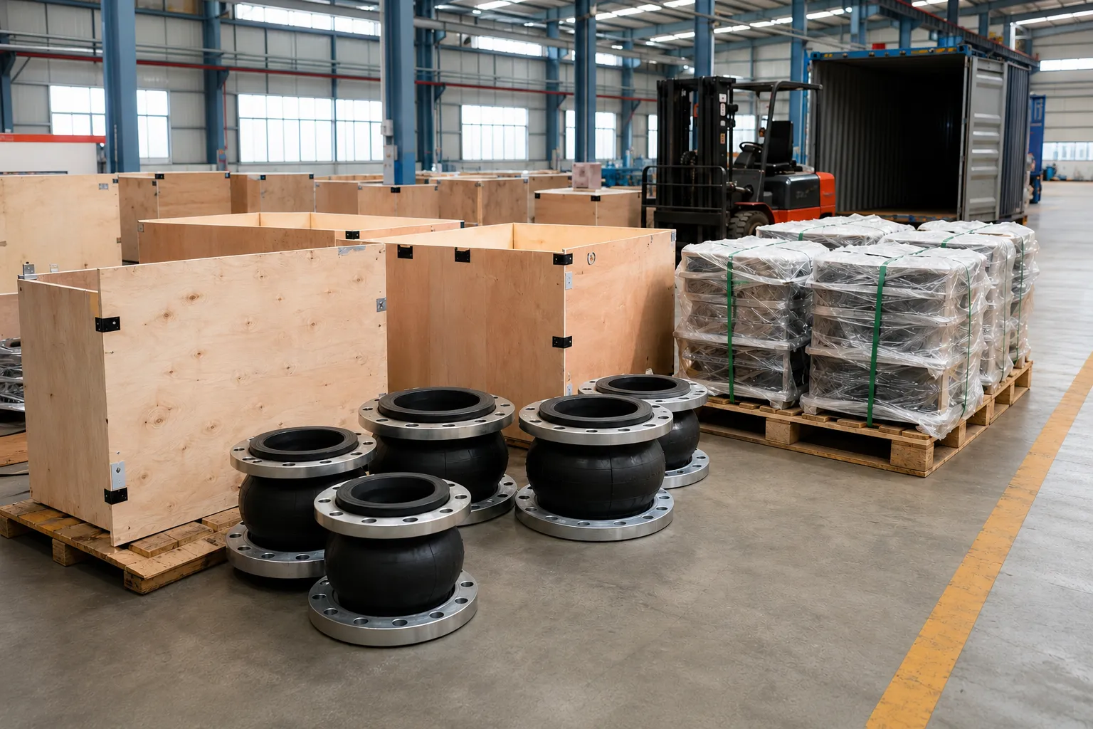
- Quantity, packaging requirements and destination port.
For non-standard dimensions, special materials, unusual flange standards or complex movement conditions, technical drawings should be reviewed before quotation.
13. Frequently Asked Questions
What is the difference between a rubber joint and a metallic bellows joint?
Rubber joints focus on vibration isolation, noise reduction and flexible connection. Metallic bellows joints are generally selected for controlled thermal movement. Final selection depends on the medium, temperature, pressure, movement and support design.
Is a dismantling joint the same as an expansion joint?
No. Both may provide installation adjustment, but dismantling joints focus on equipment removal and force transmission, while expansion joints focus on controlled pipeline movement.
Can an expansion joint absorb all pipeline thrust?
No. Thrust control depends on the joint structure, restraint devices, anchors, guides and overall piping-system design.
Why is the actual pipe outside diameter required for a flexible coupling?
Pipes with the same nominal diameter may have different outside diameters under different material and dimensional standards. The sealing and gripping range of the coupling is directly related to the actual outside diameter.
Can these products be customized?
Dimensions, materials, connection standards, coatings, identification and packaging can be customized according to project requirements. Final manufacturability must be confirmed against drawings and operating conditions.
14. Request Product Identification and Selection Support
When the product type cannot be identified from its appearance, send us installation photographs, pipe dimensions, operating conditions and project drawings. Our team can help identify the product structure and provide suitable selection, customization and quotation support.
Final dimensions, materials and technical parameters should be based on mutually confirmed drawings, datasheets, quotations or contract documents.