简体中文
简体中文  English
  日本語
日本語  한국어
한국어  Français
  Deutsch
  Español
  Português
  Русский
  العربية
  ไทย
ไทย  Tiếng Việt

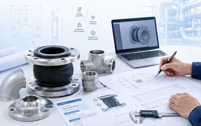
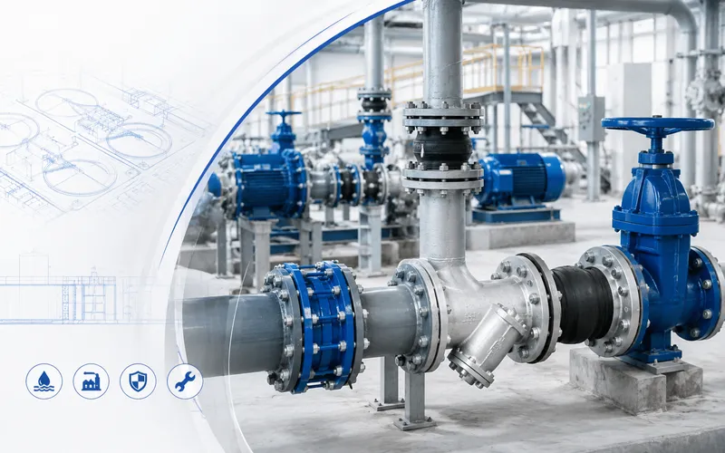
Rubber Expansion Joint Installation and Maintenance Guide
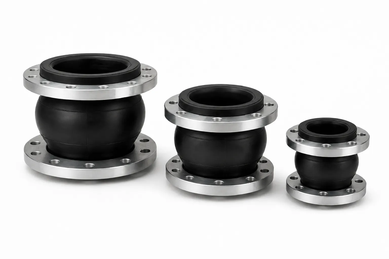
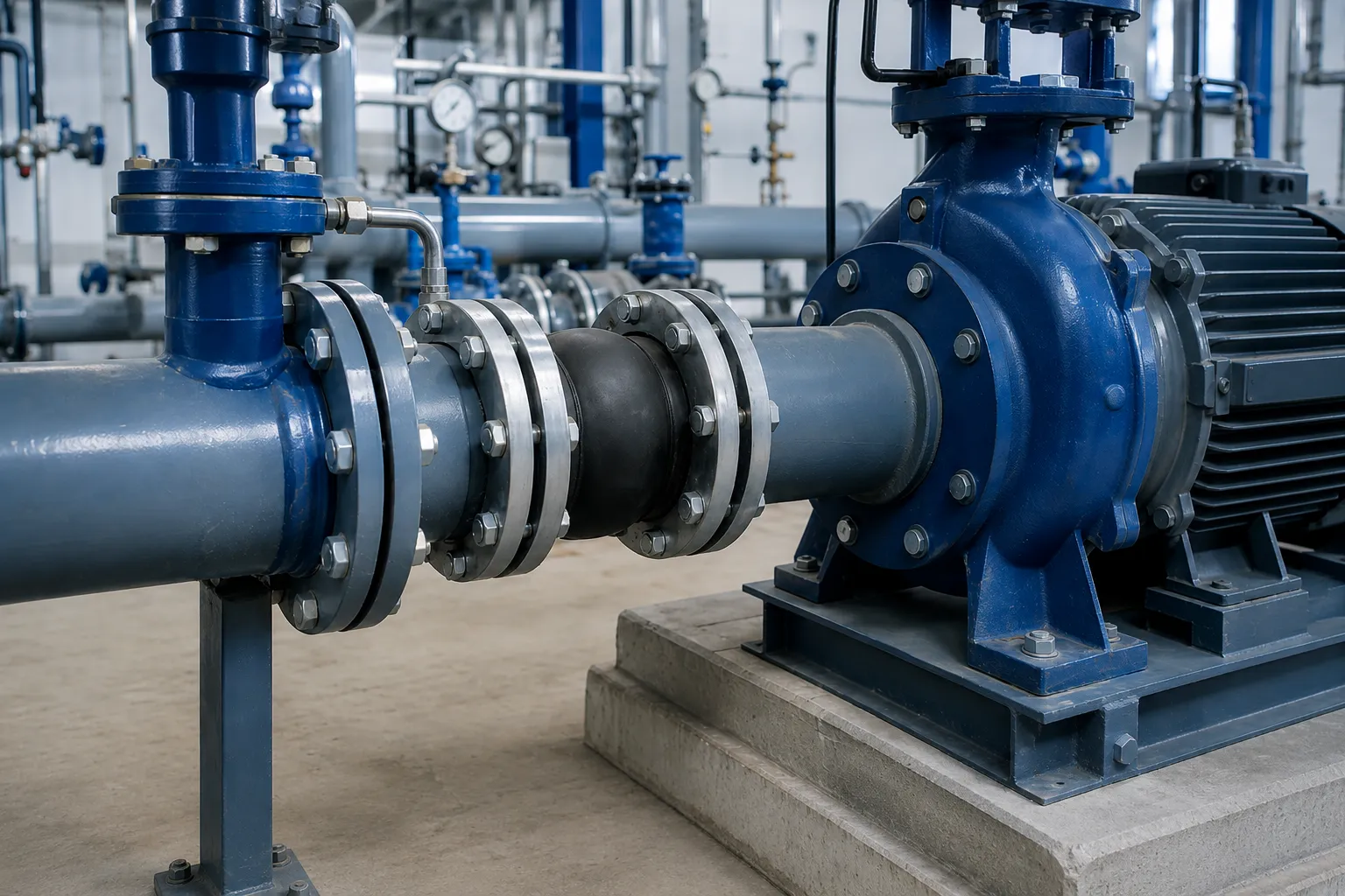
A rubber expansion joint is a flexible connector installed between pumps, valves, equipment and pipelines. Within its approved range, it can accommodate axial, lateral and angular movement while helping reduce the transmission of mechanical vibration and structure-borne noise.
Flexibility does not mean that the joint can be stretched, compressed or twisted without limitation. Misalignment, inadequate supports, incompatible flanges, incorrect installed length and improper restraint can cause leakage, abnormal deformation, reinforcement damage or connection pullout.
1. Information to Confirm Before Installation
Product Information
- Product type and construction;
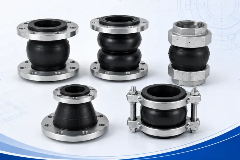
- Single sphere, double sphere, threaded or grooved design;
- Nominal size;
- Manufactured face-to-face length;
- Elastomer and operating medium;
- Operating temperature and pressure;
- Vacuum or negative-pressure suitability;
- Allowable axial, lateral and angular movement;
- Control-unit requirements;
- Approved drawing and order revision.
Piping-System Information
- Installation at pump suction, discharge or another pipeline location;
- Flange standard of the connected pipe or equipment;
- Actual distance between mating flanges;
- Pipe centreline and flange parallelism;
- Anchors, guides and pipe-support locations;
- Pressure thrust and possible surge conditions;
- Independent support of adjacent valves and equipment;
- Access for inspection and replacement.
2. Incoming Inspection and Storage
Incoming Inspection
- Verify the product type, size, quantity and order number;
- Check the rubber body for cracks, cuts or abnormal bulging;
- Check for exposed reinforcement;
- Inspect rubber flange edges and sealing areas;
- Check metallic flanges for deformation, corrosion or damaged drilling;
- Verify control rods, plates, washers and nuts where ordered;
- Inspect threaded or grooved connections;
- Confirm that the joint is not stored in a twisted or compressed condition.
Storage
- Store in a cool, dry location away from strong light;
- Keep away from heat, ozone, solvents and aggressive chemicals;
- Do not stack heavy objects on the rubber body;
- Do not restrain the sphere with tight ropes or straps;
- Avoid long-term storage in an extended, compressed or twisted condition;
- Retain product and batch identification.
3. Handling and Lifting
- Use lifting equipment suitable for the product weight;
- Lift from metallic flanges or approved lifting points;
- Do not tighten wire ropes directly around the rubber sphere;
- Do not lift from the seal, control-rod threads or rubber flange edges;
- Prevent contact with walls, supports and sharp objects;
- Do not drag the product across the floor;
- Use multiple balanced lifting points for large-diameter joints.
4. A Rubber Joint Is Not a Pipe Support
The joint provides flexibility and limited movement. It is not designed to support pumps, valves or suspended piping.
- Pumps and motors require suitable foundations;
- Valves, strainers and check valves require independent supports;
- Adjacent piping must be supported by hangers or pipe supports;
- The joint must not carry suspended pipe weight;
- Anchors and guides must control piping-system movement;
- Support settlement must not continuously extend or compress the joint.
5. Flange Compatibility and Sealing Surfaces
Confirm that the rubber-joint flange and mating flange are compatible in dimensions and sealing arrangement. The same nominal size does not guarantee identical drilling or sealing faces.
- Flange standard and pressure designation;
- Flange outside diameter;
- Bolt-circle diameter;
- Number and diameter of bolt holes;
- Sealing-face configuration;
- Clean and reasonably flat mating surfaces;
- No burrs, sharp edges, weld spatter or serious corrosion;
- Adequate support across the rubber sealing area.
Are Separate Flange Gaskets Required?
This depends on the joint-end construction and product instructions. Some integral rubber flange designs provide their own sealing surface, while other constructions may require a specified gasket.
Do not automatically add or remove a flange gasket without reviewing the applicable product drawing.
6. Installed Length and Pipe Alignment
The joint should normally be installed at its manufactured or approved neutral face-to-face length. It should not be extended to fill an excessive flange gap or overcompressed to fit an insufficient space.
Installed-Length Check
- Measure the distance between the mating flanges;
- Compare the distance with the approved face-to-face length;
- Avoid permanent pre-extension or excessive compression;
- Reserve the required operating movement;
- Follow the approved procedure where presetting is specified.
Alignment Check
- Pipe centrelines should be reasonably aligned;
- Mating flange faces should be reasonably parallel;
- Bolts should pass through without excessive side loading;
- Do not use the rubber sphere to correct severe lateral misalignment;
- Do not twist the joint to match incorrect drilling;
- Do not pull severely misaligned flanges together with bolts.
7. Flanged Rubber Expansion Joint Installation
Step 1: Isolate and Depressurize
Shut down the relevant equipment, isolate the pipeline, drain it where required and confirm that it is fully depressurized.
Step 2: Support the Equipment and Pipe
Confirm independent support of the pump, valves and adjacent piping before opening or connecting the flanges.
Step 3: Clean the Mating Flanges
Remove rust, contamination, old gasket residue, coating build-up and welding debris from the sealing area.
Step 4: Position the Joint at Neutral Length
Place the joint between the mating flanges with the rubber body in a neutral, untwisted condition.
Step 5: Confirm Orientation
Symmetrical straight joints may not have a fixed flow direction. Reducer, eccentric, lined or specially designed joints may require a defined orientation.
Step 6: Install the Bolts
Insert all flange bolts and hand-tighten the nuts. Where threaded bolt ends could approach the rubber sphere, prevent sharp threads from contacting the rubber body.
Bolt length must suit the flange thickness, washers, nuts and any control-unit plates.
Step 7: Tighten Gradually in a Cross Pattern
- Lightly tighten all bolts to position the flanges;
- Complete a second pass in a cross pattern;
- Check the rubber flange and sealing area;
- Continue tightening in controlled stages;
- Complete a final cross-pattern inspection.
Step 8: Inspect the Rubber Body
The sphere should not be twisted, locally pinched, excessively extended or in contact with bolts, supports, walls or adjacent equipment.
8. Bolt-Tightening Considerations
- Use bolts suitable for the flange drilling and construction;
- Confirm clean and undamaged threads;
- Tighten all bolts gradually and evenly;
- Keep the mating flanges reasonably parallel;
- Do not excessively extrude the rubber flange locally;
- Do not fully tighten one bolt or one side first;
- Do not apply an unsupported universal torque value;
- Investigate alignment and sealing surfaces before applying more torque.
Final torque depends on the bolt size, flange construction, rubber-end design, lubrication and approved installation instructions.
9. Control Rods and Restraint Units
Internal pressure across an unrestrained rubber joint can produce axial thrust. Where the piping system cannot reliably restrain this force, the joint may extend beyond its allowable range.
Control units should be evaluated where:
- Reliable pipe anchors are not available;
- The joint is installed near a pump or valve;
- Significant working or transient pressure is expected;
- Excessive extension or pullout is possible;
- Equipment nozzles have limited allowable loads;
- The project specification requires restraint;
- The pipeline cannot otherwise be adequately anchored.
Control-Unit Installation Principles
- Position control plates evenly according to the approved design;
- Determine rod quantity and diameter from the system conditions;
- Set nut clearances according to the permitted extension;
- Use compression sleeves where the design limits compression;
- Keep rods reasonably parallel to the piping;
- Do not reduce the number of rods;
- Do not completely lock the joint without an approved requirement;
- Do not use the control rods as supports or lifting points.
10. Pump Suction and Discharge Installations
Pump Suction
A suction line may operate below atmospheric pressure. A joint that is not designed for the vacuum condition may deform inward.
- Confirm minimum operating pressure or vacuum;
- Confirm resistance to inward collapse;
- Determine whether vacuum support is required;
- Avoid creating an air pocket near the pump inlet;
- Maintain suitable inlet-pipe alignment;
- Keep pipe weight away from the pump nozzle.
Pump Discharge
- Confirm operating and design pressure;
- Confirm anchors and guide locations;
- Evaluate control rods or anti-pullout restraint;
- Support adjacent check and isolation valves;
- Address water hammer through dedicated system measures;
- Do not transfer pipe or equipment weight to the joint.
11. Threaded and Grooved Rubber Joints
Threaded Rubber Joints
- Confirm the thread standard and male or female arrangement;
- Inspect threads for damage;
- Use a sealing method suitable for the medium and thread type;
- Prevent the rubber sphere from twisting during tightening;
- Do not apply a wrench directly to the rubber body;
- Confirm a neutral and untwisted final position.
Grooved Rubber Flexible Couplings
- Confirm groove dimensions and coupling compatibility;
- Inspect pipe grooves, seals and coupling housings;
- Align the connected pipes;
- Tighten the coupling evenly according to its instructions;
- Do not use the coupling to correct severe misalignment;
- Check for interference with the rubber body.
12. Pressure Testing and Commissioning
Inspect and test the installed piping according to the approved system procedure. Test pressure, medium, pressurization rate and holding time must follow the project documents.
Before Pressurization
- All flange bolts have been tightened as required;
- Control units are correctly set;
- Pipe, valve and equipment supports are complete;
- The rubber body is neutral and untwisted;
- Movement and inspection clearance is available;
- Venting, drainage and safety controls are confirmed.
During Pressurization
- Check for leakage at flange connections;
- Observe abnormal bulging or extension;
- Observe control rods and nuts for movement;
- Check anchors, supports and equipment for displacement;
- Confirm that the joint does not contact surrounding structures;
- Listen for abnormal noise or vibration.
If leakage or abnormal deformation occurs, stop the test and fully depressurize the pipeline before adjustment.
13. Inspection and Maintenance
Initial Operating Inspection
- Check the flange connections for leakage;
- Check for visibly loose bolts;
- Check for abnormal extension or compression;
- Inspect piping and support settlement;
- Review bolt tightness where required by the product instructions.
Periodic Inspection
- Cracks, cuts or ageing of the rubber surface;
- Abnormal bulges, depressions or separation;
- Exposed reinforcement;
- Continuing flange leakage;
- Abnormal extension, compression, twisting or lateral displacement;
- Corroded or deformed rods, plates, washers and nuts;
- Damaged coatings and metallic corrosion;
- Movement of anchors, supports and equipment foundations;
- Operating conditions beyond the original selection basis.
Conditions Requiring Technical Review or Replacement
- Significant cracking of the rubber body;
- Exposed reinforcement;
- Persistent leakage;
- Severe permanent deformation;
- Damaged flanges or restraint components;
- Chemical, flame or welding damage;
- Major changes in the piping operating conditions.
14. Common Installation Mistakes
- Stretching the joint to fill an excessive flange gap;
- Installing it in an overcompressed condition;
- Twisting the joint to match incorrect flange drilling;
- Pulling severely misaligned flanges together with bolts;
- Allowing the joint to support pipe, valve or equipment weight;
- Installing against sharp, damaged or contaminated flange faces;
- Adding or removing a gasket without checking the product design;
- Tightening continuously around the flange instead of using a cross pattern;
- Allowing long bolts to contact the rubber sphere;
- Applying an unsupported universal bolt torque;
- Operating without adequate anchors or restraint;
- Removing control rods or changing nut positions without approval;
- Using the joint under vacuum without confirming suitability;
- Treating the joint as a stand-alone water-hammer device;
- Exposing the rubber to welding sparks, paint or solvents;
- Adjusting the joint while the pipeline is pressurized.
15. Pre-Installation Checklist
| Category | Items to Confirm |
|---|---|
| Product | Type, size, materials, face-to-face length and service |
| Flanges | Standard, drilling, sealing face and end construction |
| Site Gap | Matches the approved neutral installed length |
| Alignment | Centreline, parallelism and bolt-hole position |
| Supports | Independent support for pipes, valves, pumps and equipment |
| Restraint | Anchors, pressure thrust and control-unit requirements |
| Bolts | Size, length, orientation and tightening procedure |
| Safety | Shutdown, isolation, depressurization, drainage and permits |
| Access | Operating movement, inspection and replacement clearance |
16. Information Required for Selection and Quotation
- Product type and installation position;
- Nominal size;
- Required neutral face-to-face length;
- Operating medium and composition;
- Normal and maximum temperature;
- Operating pressure, design pressure and possible vacuum;
- Flange, thread or groove standard;
- Axial, lateral and angular movement;
- Anchor and guide conditions;
- Control-unit or vacuum-support requirements;
- Elastomer and metallic material requirements;
- Project drawings, photographs or equipment interfaces;
- Inspection, documentation and packing requirements;
- Quantity and destination port.
17. Frequently Asked Questions
Can a rubber expansion joint correct pipe misalignment?
It should not be used to correct severe lateral, angular or flange-parallelism errors. The pipe and equipment flanges must be correctly aligned before installation.
Is a separate flange gasket required?
It depends on the end and sealing construction. Follow the applicable product drawing and installation instructions.
Can the joint support a valve or pipe?
No. Pumps, valves, pipes and equipment require independent supports.
Are control rods always required?
Not always. Their need depends on pressure thrust, anchors, allowable equipment loads and pullout risk.
Can the joint be adjusted under pressure?
No. Isolate and fully depressurize the pipeline before making adjustments or opening connections.
How often should the joint be inspected?
Initial and periodic inspection intervals should be determined from the operating medium, pressure, temperature, equipment cycles, environment and maintenance programme.
18. Request Installation and Selection Support
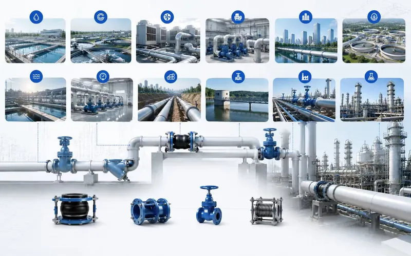
For pump stations, water treatment, water supply, HVAC or industrial piping, provide the piping layout, site photographs, flange standard, medium, temperature, pressure, installed length and movement requirements.
We can assist with evaluating single sphere, double sphere, threaded or grooved rubber expansion joints, together with materials, restraint and installation requirements.
Final installed length, bolt-tightening requirements, control-unit settings and acceptance criteria must follow mutually approved drawings, datasheets, installation instructions, purchase orders and project documents.