简体中文
简体中文  English
  日本語
日本語  한국어
한국어  Français
  Deutsch
  Español
  Português
  Русский
  العربية
  ไทย
ไทย  Tiếng Việt

Dismantling Joint Installation Guide for Valves and Flanged Equipment
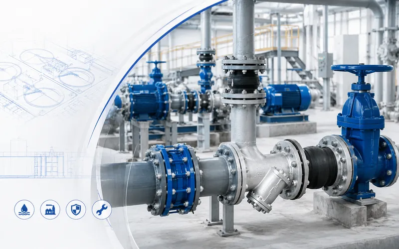
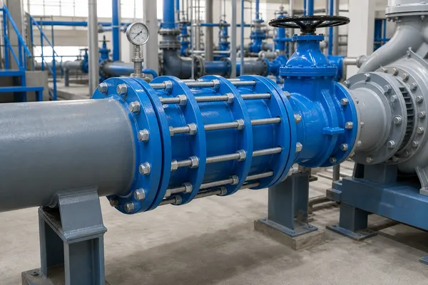
A double-flange dismantling joint is commonly installed beside butterfly valves, gate valves, check valves, flow meters, pumps and other flanged equipment. The telescopic section provides controlled axial adjustment during installation and creates clearance for equipment removal during future maintenance.
After the flanges, sealing system and tie rods have been correctly assembled, the joint forms a restrained connection capable of transmitting axial forces within its approved design conditions. It does not replace pipe anchors, guides, valve supports or the complete piping-load design.
1. What Is a Double-Flange Dismantling Joint?
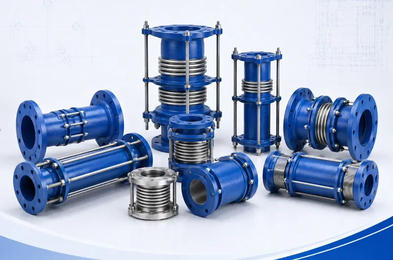
A dismantling joint is a steel pipeline connector installed between two flanged connection faces. A typical construction includes a main body, telescopic spigot, sealing ring, gland, flanges and longitudinal tie rods or connecting bolts.
Relative movement between the telescopic components allows the face-to-face length to be adjusted during installation. After the flanges, gland and tie rods are secured, the assembly becomes a restrained connection.
Main Functions
- Accommodate limited installation-length tolerances;
- Simplify the installation of valves, pumps and flanged equipment;
- Create axial clearance for future equipment removal;
- Reduce field cutting and rewelding;
- Transmit axial forces through the approved restraint structure;
- Provide a defined maintenance point in the pipeline.
The adjustment range is primarily intended for installation and dismantling. It should not automatically be treated as unrestricted operating movement.
2. Why Install a Dismantling Joint Beside a Valve?
Large butterfly valves, gate valves, check valves and flow meters are normally secured between fixed flanged pipe sections. Without an adjustable component, there may be insufficient clearance to separate the flanges and remove the equipment.
A dismantling joint can be shortened after the pipeline has been isolated, depressurized and properly supported. This creates clearance for removing flange bolts, gaskets and the valve.
Typical Locations
- Beside butterfly valves;
- Beside gate valves;
- Beside check valves;
- Beside flow meters;
- Beside strainers and equipment requiring cleaning;
- Near pump discharge valve assemblies;
- At water-treatment equipment connections;
- In pipeline and pump-station rehabilitation projects.
3. Typical Valve Arrangements
Another arrangement may be used where maintenance access requires it:
In either arrangement, confirm that:
- The valve has independent and adequate support;
- The joint does not carry valve or pipe weight;
- Axial clearance is available in the removal direction;
- The valve actuator and lifting points remain accessible;
- The mating flanges are correctly aligned;
- Bolts and tie rods remain accessible for maintenance;
- Anchors and supports meet the pipeline-load requirements.
4. Technical Information to Confirm Before Installation
Joint Information
- Product type and model;
- Nominal size;
- Approved face-to-face adjustment range;
- Working-pressure conditions or pressure designation;
- Body, flange, gasket and tie-rod materials;
- Flow or installation direction where applicable;
- Approved drawing and revision.
Flange Information
- Compatibility of valve, pipe and dismantling-joint flanges;
- Flange outside diameter;
- Bolt-circle diameter;
- Number and diameter of bolt holes;
- Flange thickness;
- Sealing-face type;
- Required flange-gasket dimensions and material.
Site Conditions
- Actual distance between the mating flanges;
- Flange centreline and elevation;
- Flange alignment and parallelism;
- Independent support of the valve and pipe;
- Lifting and bolt-access space;
- Required direction for future valve removal;
- Confirmation that the pipeline is safely isolated and depressurized.
5. Safety Preparation
- Shut down and lock out pumps, valves and related equipment;
- Confirm that the pipeline is fully depressurized;
- Drain process fluid where required;
- Control hot, corrosive, toxic or flammable-fluid hazards;
- Install blinds or another approved isolation method where required;
- Support the valve and pipe before loosening any connection;
- Prepare suitable lifting equipment, hand tools and approved torque tools;
- Establish a controlled work area.
Never loosen flange bolts, gland bolts or tie rods while the pipeline remains pressurized.
6. Product Inspection Before Installation
- Verify the product model, size, quantity and project identification;
- Inspect flanges, body, telescopic section and gland for deformation;
- Check sealing faces for impact damage, corrosion or coating build-up;
- Confirm that tie rods, bolts, nuts and washers are complete;
- Inspect the sealing ring for damage, contamination or twisting;
- Confirm that the telescopic section is not visibly obstructed;
- Inspect the coating for serious transport damage;
- Confirm that drawings, instructions and ordered accessories are available.
Do not completely disassemble an assembled dismantling joint unless the product instructions specifically require it. Unnecessary disassembly can lead to incorrect seal orientation or component reassembly.
7. Step-by-Step Installation Beside a Valve
Step 1: Support the Valve and Piping
The valve, adjacent pipework and dismantling joint must be supported by foundations, pipe supports, hangers or suitable temporary lifting equipment. The dismantling joint must not carry suspended equipment weight.
Step 2: Measure the Flange Gap
Measure the actual distance between the valve flange and the pipeline flange. Confirm that the distance is within the approved adjustment range.
Do not solve an excessive or insufficient gap by overstretching the joint, overcompressing it or using unsuitable extended bolts.
Step 3: Check Alignment
The two mating flanges should be reasonably concentric and parallel. A dismantling joint provides axial adjustment, but it should not be used to correct severe lateral, angular or elevation misalignment.
Step 4: Pre-Adjust the Length
Loosen the appropriate adjustment nuts or gland components and set the joint to a length suitable for positioning between the mating flanges.
Keep the telescopic section reasonably concentric to prevent the sealing ring from rolling, extruding or becoming trapped.
Step 5: Lift the Joint into Position
Use lifting equipment appropriate for the product weight and construction. Do not lift the product from the seal, threaded ends of tie rods or components that can be damaged or distorted.
Step 6: Install Flange Gaskets
Install suitable flange gaskets between the valve and dismantling joint and between the dismantling joint and pipeline flange.
The gasket material must be compatible with the medium, temperature, pressure and flange face. Confirm whether gaskets are included in the ordered supply scope.
Step 7: Connect the First Flange
Position the first side against the valve or pipe flange. Insert the bolts and hand-tighten them sufficiently to hold the assembly without fully locking it.
Step 8: Adjust the Length and Connect the Second Flange
Extend or collapse the telescopic section smoothly until the second flange reaches the mating flange. Do not use flange bolts to force widely separated or misaligned flanges together.
Confirm that the gasket is centred, the flange faces contact evenly and the bolts pass through without excessive side loading.
Step 9: Initially Tighten Both Flange Connections
Tighten the flange bolts gradually in a cross pattern. Do not fully tighten one side or proceed continuously around the circumference.
Step 10: Tighten the Gland or Sealing Components
Tighten the gland bolts evenly so the sealing ring is compressed uniformly around the telescopic section. Keep the gland reasonably parallel throughout tightening.
Step 11: Secure the Tie Rods
After confirming the installation length, flange connections and seal arrangement, set and tighten the tie rods, nuts and washers according to the approved drawing.
Tie-rod function and required clearances vary by design. Do not remove, lock or loosen them without technical instructions.
Step 12: Complete the Final Inspection
- Face-to-face length matches the approved requirement;
- Mating flanges are reasonably aligned and parallel;
- Flange gaskets remain centred;
- The gland is evenly positioned;
- All specified bolts have been tightened;
- Tie rods and accessories are correctly installed;
- The valve, pipe and joint are properly supported;
- No surrounding component obstructs operation or maintenance.
8. Understand the Different Fasteners
| Fastener | Primary Function | Installation Consideration |
|---|---|---|
| Flange bolts | Connect the valve, joint and pipeline flanges | Tighten evenly in a cross pattern and check the gasket |
| Gland bolts | Compress the sealing ring around the telescopic section | Tighten in stages and keep the gland parallel |
| Tie rods and nuts | Restrain the connection and transmit approved axial forces | Set according to the product drawing; do not alter them arbitrarily |
Some designs use continuous tie rods passing through the adjacent valve and pipeline flanges. Other products use a different restraint arrangement. Always identify each fastener from the applicable product drawing.
9. Bolt-Tightening Principles
- Install all bolts by hand and confirm correct thread engagement;
- Apply an initial low tightening load to position the components;
- Increase tightening gradually in a cross pattern;
- Check flange gaps and gland parallelism after each stage;
- Complete tightening to the approved final torque;
- Repeat the specified sequence for a final check;
- Inspect after testing or initial operation where the procedure requires it.
Final torque depends on bolt size, gasket type, lubrication, flange construction and project requirements. Do not apply an unsupported universal torque value or use excessive torque to correct misalignment.
10. Pressure Testing and Commissioning
After installation, inspect and test the pipeline according to the approved system-test procedure. Test pressure, medium, pressurization rate and holding time must follow the applicable project documents.
Before Pressurization
- Remove temporary tools and lifting equipment not required for testing;
- Confirm final valve and pipe supports;
- Recheck flanges, gland bolts and tie rods;
- Confirm venting, drainage and safety isolation;
- Keep personnel clear of potential leakage and movement zones.
Observe During Testing
- Leakage at either flange connection;
- Leakage at the gland seal;
- Unexpected telescopic movement;
- Deformation of tie rods, nuts or flanges;
- Movement of valve or pipe supports;
- Abnormal noise or structural change.
If leakage occurs, stop the test and fully depressurize the pipeline before making any adjustment.
11. Using the Joint to Remove a Valve
- Shut down and isolate the pipeline section;
- Confirm full depressurization and drainage;
- Support the valve and adjacent piping independently;
- Mark the tie-rod, nut and telescopic positions;
- Release the required components gradually according to the instructions;
- Keep the remaining connections under control to prevent sudden movement;
- Collapse the joint to create flange-removal clearance;
- Remove the flange bolts and gaskets;
- Lift the valve using suitable equipment;
- Protect the joint, flange faces and telescopic sealing area.
When reinstalling the valve, use suitable replacement flange gaskets and repeat the alignment, length, gland and tie-rod checks.
12. Inspection and Maintenance
- Leakage at flange and gland locations;
- Loose or corroded tie rods, nuts, washers and bolts;
- Deformation of the body, telescopic section or flanges;
- Damaged coating or significant corrosion;
- Settlement or movement of valves, pipes and supports;
- Abnormal extension or compression of the joint;
- Impact, standing water or chemical-corrosion risks;
- Changes in pressure or medium from the original selection basis.
Continuing leakage, deformed tie rods, damaged threads, abnormal seal movement or serious body corrosion require isolation, depressurization and technical inspection.
13. Common Installation Mistakes
- Using the joint to correct lateral pipe misalignment;
- Pulling non-parallel flanges together with bolts;
- Using a flange gap outside the approved adjustment range;
- Allowing the joint to support valve or pipe weight;
- Omitting or incorrectly installing flange gaskets;
- Twisting, pinching or incorrectly positioning the sealing ring;
- Overtightening one side of the gland;
- Confusing flange bolts, gland bolts and tie rods;
- Removing or reducing the number of tie rods;
- Failing to tighten flange bolts in a cross pattern;
- Ignoring product working-pressure limitations;
- Adjusting the joint while the pipeline is pressurized;
- Removing a valve without independent lifting and support;
- Reusing damaged or incompatible flange gaskets;
- Failing to reserve axial and lifting clearance for maintenance.
14. Pre-Installation Checklist
| Category | Items to Confirm |
|---|---|
| Product | Model, size, pressure conditions, length and materials |
| Flanges | Standard, drilling, sealing face and gaskets |
| Site Gap | Within the approved adjustment range |
| Alignment | Centreline, elevation, parallelism and drilling |
| Supports | Independent support for the valve, pipe and joint |
| Sealing | Seal and flange-gasket material, size and condition |
| Fasteners | Bolts, tie rods, nuts, washers and corrosion protection |
| Maintenance | Removal direction, lifting access and working clearance |
| Safety | Shutdown, isolation, depressurization, drainage and permits |
15. Information Required for Selection and Quotation
- Nominal size of the dismantling joint;
- Valve and pipeline flange standard;
- Required face-to-face length or measured flange gap;
- Operating medium;
- Normal operating temperature;
- Operating and design pressure;
- Body, flange, seal and tie-rod material requirements;
- Coating and corrosion-protection requirements;
- Valve type and installation position;
- Pipe supports, anchors and axial-loading conditions;
- Required gaskets, bolts or accessories;
- Inspection, testing and documentation requirements;
- Project drawings, site photographs or equipment drawings;
- Quantity, packing requirements and destination port.
16. Frequently Asked Questions
Which side of a valve should the dismantling joint be installed on?
There is no universal position. Select the side according to the piping arrangement, maintenance direction, lifting space, anchors, flow arrangement and approved project drawings.
Can a dismantling joint correct pipe misalignment?
It primarily provides axial installation adjustment. It should not be used to correct significant lateral, angular or flange-parallelism errors.
Can the joint support the valve?
No. Valves, pipes and equipment require independent supports, foundations or lifting arrangements.
Are flange gaskets required?
Suitable flange gaskets are normally required between the valve, dismantling joint and pipeline flanges. Confirm whether they are included in the ordered supply scope.
Can every fastener use the same torque?
No general assumption should be made. Flange bolts, gland bolts and tie rods have different functions, sizes and tightening requirements.
Can the joint be loosened while the pipeline is pressurized?
No. The pipeline must be shut down, isolated, fully depressurized and drained, and the valve and pipe must be independently supported.
17. Request Selection and Installation Support
For pump stations, water-transmission pipelines, wastewater treatment, water-treatment equipment or large-valve installations, provide the valve drawing, flange standard, site gap, medium, temperature, pressure and piping-layout information.
We can assist with confirming the connection type, face-to-face length, materials, sealing arrangement, tie-rod configuration, coating and packing requirements.
Final construction, installation method, tightening requirements and acceptance criteria must follow mutually approved drawings, datasheets, installation instructions, purchase orders and project documents.