简体中文
简体中文  English
  日本語
日本語  한국어
한국어  Français
  Deutsch
  Español
  Português
  Русский
  العربية
  ไทย
ไทย  Tiếng Việt

How to Choose Rubber Expansion Joints for Pump Stations
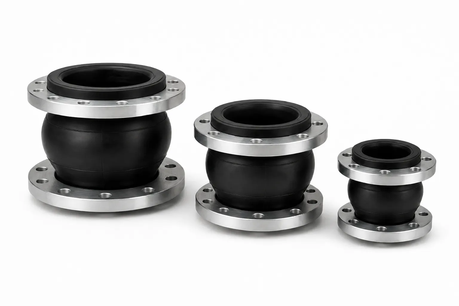
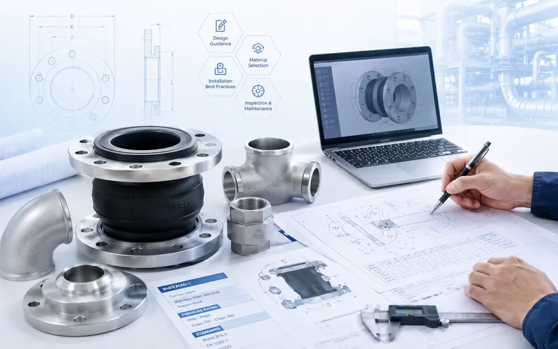
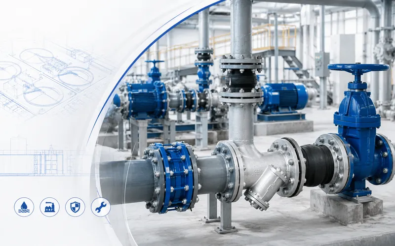
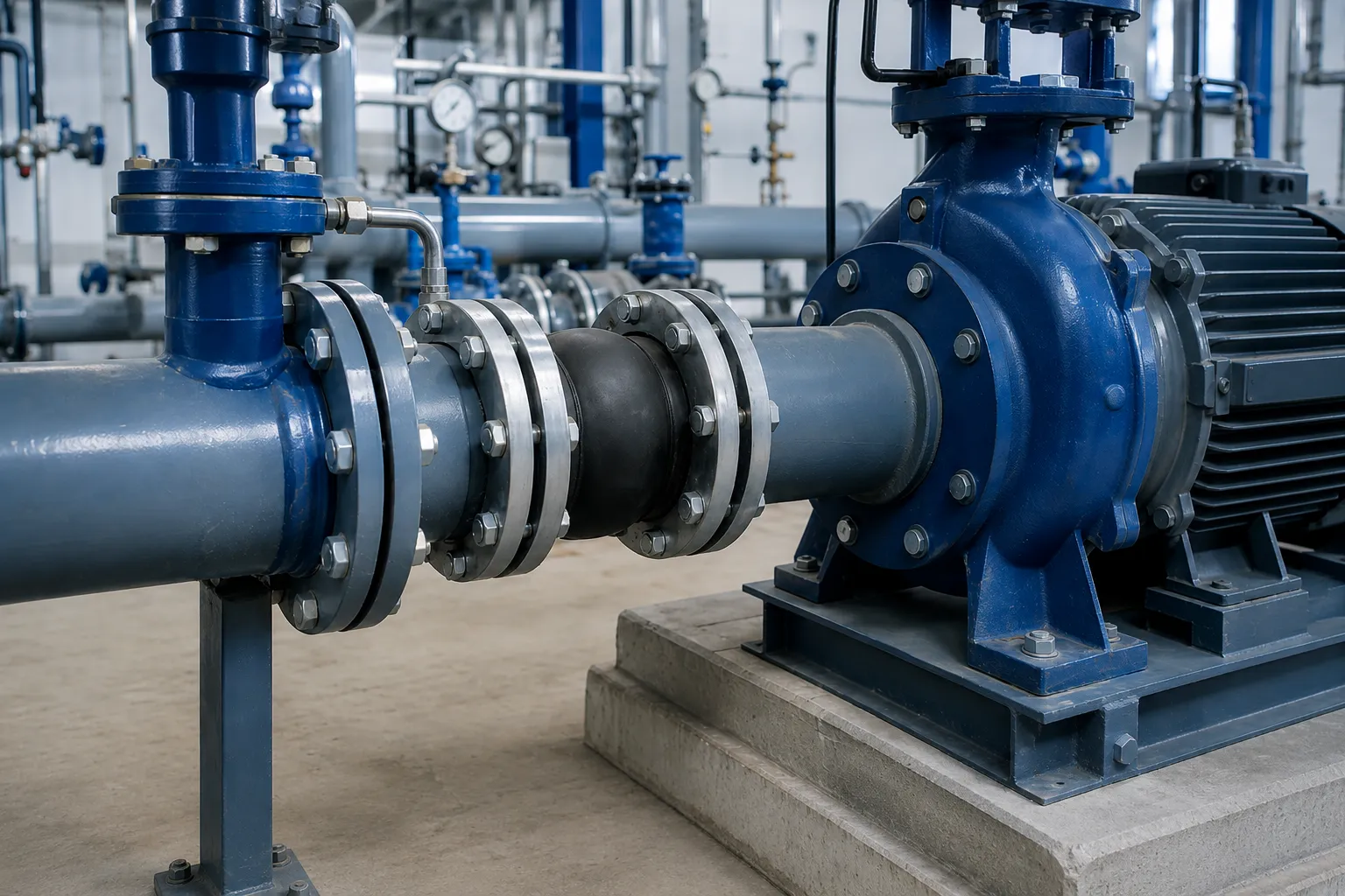
Rubber expansion joints are commonly installed between pumps, valves, treatment equipment and pipelines to provide flexibility, isolate part of the mechanical vibration and accommodate limited movement within an approved range.
Pump-station joints should not be selected only by nominal size, sphere quantity or product photographs. Suction and discharge lines have different pressure, flow and thrust conditions, while medium, temperature, flange standard, installed length, anchors and transient pressure can all affect the required construction.
1. Why Pump-Station Joints Require Application-Specific Selection
Pump-station piping can be affected by equipment vibration, pipe weight, pump starting and stopping, pressure thrust, installation tolerances and maintenance access. The rubber expansion joint forms part of this complete piping system.
Incorrect selection may result in:
- Inward collapse of the rubber body on the suction side;
- Excessive extension caused by discharge-side pressure thrust;
- Swelling, hardening or cracking caused by incompatible media;
- Incorrect flange drilling or face-to-face length;
- Long-term pipe or valve weight applied to the joint;
- Combined movement beyond the approved capability;
- Water hammer or system vibration incorrectly assigned to the joint;
- Forced stretching, compression or twisting during installation.
2. Ten Items to Confirm Before Selection
- Installation position: pump suction, discharge, valve or pipeline.
- Nominal size: DN, NPS and required interface dimensions.
- Medium: clean water, wastewater, seawater, oil-containing or chemical fluid.
- Temperature: normal, maximum, minimum and continuous conditions.
- Pressure: operating, design and transient pressure.
- Vacuum: minimum suction-line pressure or vacuum condition.
- Connection: flange, thread or groove standard.
- Installed length: actual interface distance and available space.
- Movement: axial, lateral, angular and combined movement.
- Piping loads: anchors, guides, equipment supports and restraint.
3. Identify the Installation Position
| Position | Main Purpose | Main Risk |
|---|---|---|
| Pump suction | Flexible connection and vibration isolation | Vacuum collapse, flow disturbance, air pockets and support |
| Pump discharge | Vibration isolation and limited movement | Pressure thrust, transient pressure and pullout |
| Near a valve or check valve | Flexible equipment transition | Valve weight, support and maintenance access |
| Treatment equipment | Reduce vibration and nozzle loading | Medium compatibility and allowable equipment loads |
| Pump-station pipeline | Flexible connection and limited movement | Thermal movement, anchors, guides and combined movement |
Rubber joints are not automatically required on both sides of every pump. The arrangement should be evaluated according to pump type, vibration source, allowable nozzle load, piping layout and project specification.
4. Single Sphere or Double Sphere?
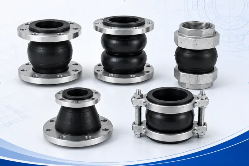
Single Sphere Rubber Expansion Joint
A single sphere joint has one elastomeric arch and normally provides a compact flanged connection. It is commonly evaluated for pump stations, treatment equipment and general water piping.
It may be considered first where:
- Installation space is limited;
- Normal vibration isolation and limited movement are required;
- The pump and pipe use flanged connections;
- A standard face-to-face length is required;
- Anchoring and support conditions are clearly defined.
Double Sphere Rubber Expansion Joint
A double sphere joint has two connected arches and different flexibility, length and load characteristics. It may provide a different movement profile, but it is not automatically superior for every pump station.
| Project Condition | Initial Direction |
|---|---|
| Compact pump connection | Evaluate a single sphere design first |
| Different flexibility or movement requirement | Compare specific single and double sphere data |
| Unclear thrust or anchoring | Review loads and restraint before changing sphere quantity |
| Complex combined movement | Submit movement and piping-layout information |
5. Pump Suction-Side Selection
A pump suction line may operate below atmospheric pressure. If the rubber joint is not designed for the actual vacuum condition, the sphere may deform inward and reduce the effective flow area.
Confirm the Following
- Minimum internal pressure during normal operation;
- Vacuum during startup, shutdown and abnormal operation;
- Approved resistance to inward collapse;
- Need for a vacuum-support ring or reinforced construction;
- Possible impact on the pump-inlet flow path;
- Potential air-pocket locations;
- Independent support of upstream piping and valves;
- No initial twisting or eccentric deformation.
6. Pump Discharge-Side Selection
The discharge side normally operates under positive pressure. Internal pressure acting across a flexible joint can generate axial thrust and extend an inadequately restrained joint.
Confirm the Following
- Normal operating pressure;
- Design pressure and testing requirements;
- Transient pressure during pump startup and shutdown;
- Pressure changes caused by check and control valves;
- Anchor and guide locations;
- Need for control units or anti-pullout restraint;
- Allowable pump and valve nozzle loads;
- Independent support of valves and adjacent piping.
A rubber expansion joint is not a stand-alone water-hammer control device. Water hammer should be addressed through pump control, valve characteristics, surge-control equipment, air management and complete hydraulic design.
7. Select the Elastomer According to the Medium
EPDM-Type Elastomer
EPDM is commonly evaluated first for clean water, water supply, circulation water, selected HVAC systems and outdoor water-piping applications.
NBR-Type Elastomer
NBR is commonly evaluated first for mineral oils, lubricants and selected oil-containing media. The exact oil, additives, concentration and temperature must be confirmed.
Wastewater and Process Water
Wastewater should not be classified simply as water. Industrial wastewater may contain oils, solvents, cleaning agents, acids, alkalis and solids.
Seawater
Seawater service also requires review of flange, control-rod, fastener and coating corrosion protection.
Potable Water
EPDM identification alone does not confirm potable-water compliance. The specific compound and required project documentation must be verified.
8. Do Not Select by Flange Rating Alone
PN16, Class 150 and JIS 10K are part of flange or standard rating systems. They do not independently prove the suitability of the rubber body under every temperature and medium.
Review:
- Operating pressure;
- Design pressure;
- System-test pressure;
- Transient pressure;
- Medium temperature;
- Nominal size;
- Rubber body and reinforcement;
- Flange and control-unit construction;
- Possible suction-side vacuum.
9. Define the Required Movement
Axial Compression
The connection points move toward each other along the pipe axis.
Axial Extension
The connection points move apart. Extension requires particular attention to pressure thrust and pullout risk.
Lateral Movement
The two centrelines remain approximately parallel but shift sideways.
Angular Movement
The connection faces rotate through a limited angle. The joint should not remain twisted.
Combined Movement
Maximum movement values in different directions should not automatically be added together. Combined movement requires confirmation against specific product data.
10. Flange Standard and Face-to-Face Length
Flange Standard
Pump-station projects may use EN, ASME, JIS, AWWA, BS or GB flange systems. Equal nominal size does not guarantee equal drilling or facing.
Provide:
- Complete flange standard;
- DN or NPS size;
- PN, Class, K or another rating;
- Flange facing;
- Mating pump, valve or pipe drawing;
- Outside diameter, bolt circle, hole quantity and hole diameter.
Face-to-Face Length
The rubber joint should normally be installed at its approved neutral face-to-face length. Do not overstretch it to fill an excessive gap or continuously compress it into insufficient space.
11. When Are Control Units Required?
Where properly designed anchors resist pressure thrust, the piping system may not rely on joint-mounted restraint. Where anchoring is inadequate or overextension is possible, control units should be evaluated.
Particular attention is required where:
- Discharge pressure or pressure fluctuation is significant;
- Reliable pipe anchors are not available;
- The joint is close to a pump, valve or equipment nozzle;
- Overextension or pullout is possible;
- Equipment has low allowable nozzle loads;
- The pipe is suspended, vertical or difficult to anchor;
- The project specification requires control units.
Rod quantity, diameter, plate thickness, nut position and clearance depend on the joint size, pressure, flange construction and piping loads.
12. Preliminary Selection by Pump-Station Application
| Application | Initial Product Direction | Key Confirmation |
|---|---|---|
| Municipal clean-water station | Single sphere or specified flanged joint | EPDM direction, flange, pressure and anchoring |
| Wastewater lift station | Select elastomer from actual wastewater | Oil, chemicals, solids and maintenance |
| Pump suction line | Vacuum-confirmed construction | Minimum pressure and inward-collapse resistance |
| Pump discharge line | Flanged joint with restraint where required | Pressure thrust, transients and anchors |
| Seawater station | Application-specific rubber and metallic materials | Compatibility and external corrosion protection |
| Oil-containing industrial station | NBR or another oil-resistant direction | Oil composition, additives and temperature |
| Small auxiliary piping | Threaded or compatible grooved joint | Connection standard, size, pressure and support |
13. Review Supports and Equipment Loads
The rubber joint must not support pumps, valves, strainers or suspended piping. Incorrect supports can damage a correctly selected joint.
- Pumps and motors have stable foundations;
- Suction and discharge pipes have independent supports;
- Check valves, isolation valves and strainers are independently supported;
- Anchors can resist the design axial thrust;
- Guides control the expected direction of movement;
- Support settlement will not continuously extend or compress the joint;
- Movement and inspection clearance is available;
- Equipment-nozzle loads remain within the approved limits.
14. Common Selection Mistakes
- Selecting only by DN and PN;
- Using the same joint automatically on both pump sides;
- Omitting suction-side vacuum information;
- Assuming a double sphere is always better;
- Identifying EPDM or NBR by colour;
- Ignoring oil and chemical content in wastewater;
- Treating the flange rating as the complete product rating;
- Ignoring discharge-side pressure thrust;
- Operating without confirmed anchors or control units;
- Confusing installation adjustment with operating movement;
- Adding maximum movement values in different directions;
- Using the joint to correct severe pipe misalignment;
- Allowing it to support valves or piping;
- Adding a joint as the only water-hammer solution;
- Omitting the flange standard and installed length.
15. Information Required for an RFQ
- Pump-station type and installation position;
- Pump suction or discharge connection size;
- Nominal joint size;
- Medium, composition and concentration;
- Normal, maximum and minimum temperature;
- Operating and design pressure;
- Suction-side minimum pressure or vacuum;
- Transient-pressure or surge information where available;
- Flange, thread or groove standard;
- Required face-to-face length and available space;
- Axial, lateral and angular movement;
- Installation or operating movement;
- Anchors, guides and equipment supports;
- Control-unit or vacuum-support requirement;
- Elastomer, flange and fastener materials;
- Coating and outdoor-environment requirements;
- Pump drawings, piping layout and site photographs;
- Quantity, documentation, packing and destination.
16.Request Pump-Station Selection Support
For municipal water, wastewater, water treatment, industrial circulation, seawater or other pump stations, provide the pump drawing, piping layout, photographs, medium, temperature, pressure, flange standard and available installation length.
We can assist with evaluating single sphere, double sphere, threaded or grooved rubber expansion joints, together with elastomer, vacuum, connection and restraint requirements.
Final construction, dimensions, materials, pressure, vacuum capability, movement and suitability must follow mutually approved drawings, datasheets, quotations or purchase contracts.