 简体中文
简体中文  English
  日本語
日本語  한국어
한국어  Français
  Deutsch
  Español
  Português
  Русский
  العربية
  ไทย
ไทย  Tiếng Việt



单波纹管轴向补偿
由一个金属波纹管及两端连接件组成,主要用于吸收轴向压缩和轴向伸长。

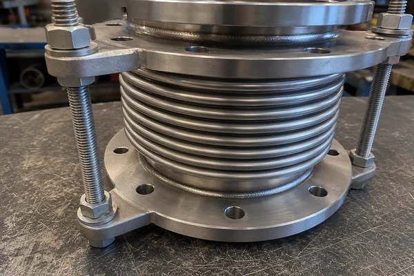
The single axial metal bellows expansion joint consists of one bellows element, two end connections and limit-rod assemblies. It is primarily used to absorb axial compression and extension caused by temperature changes in straight pipe runs. The limit rods control the permitted movement range and provide over-travel protection, while anchors, guides and pressure-thrust management must still be confirmed by the piping design.
This limit-rod axial design still requires proper main anchors, pipe guides and pressure-thrust checks in the piping system.
Metal Bellows Expansion Joints
A limit-rod controlled metal bellows expansion joint for axial compression and extension in straight pipe runs. It is commonly selected for steam, hot water, district heating and industrial process pipelines where axial thermal movement must be absorbed. The joint itself does not balance pressure thrust, so anchors, guides, movement value, medium, pressure, temperature and end connection must be confirmed during selection.
Limit-rod structure note: This is a single axial metal bellows expansion joint with limit rods. The limit rods control the permitted axial travel and provide over-travel protection. The unit remains primarily intended for axial movement, while pipe anchors, guides and pressure-thrust management must be confirmed by the project piping design. The limit rods should not be assumed to continuously carry all normal pressure thrust, and this unit is not a pressure-balanced expansion joint. Rod gap, nut position, rod diameter, allowable load and abnormal-load duty are pending manufacturer drawing confirmation.
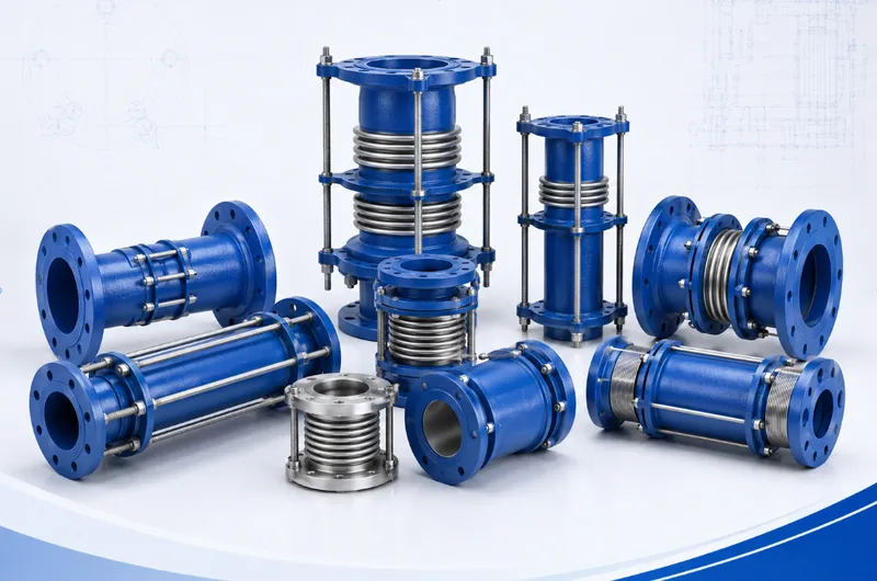
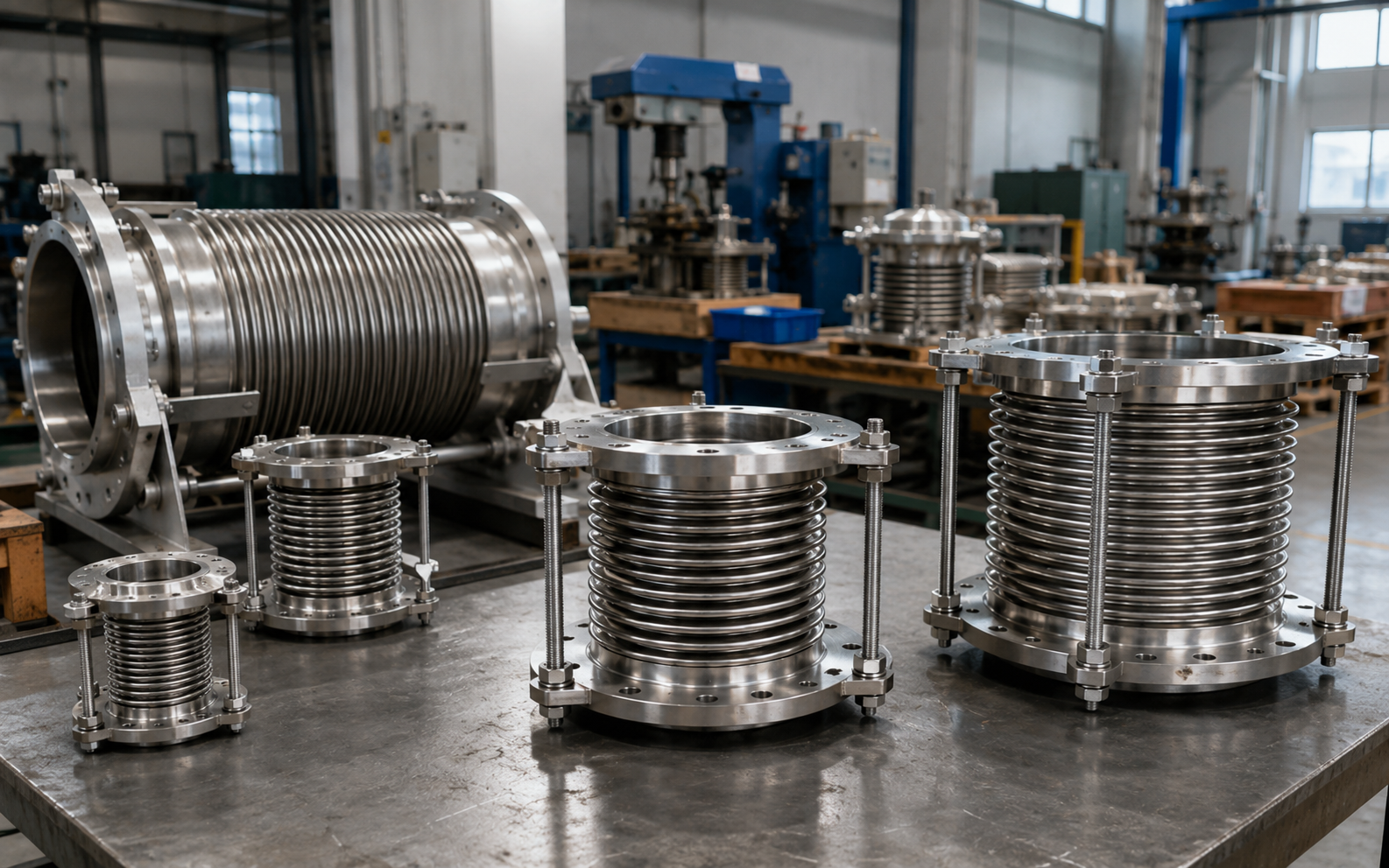
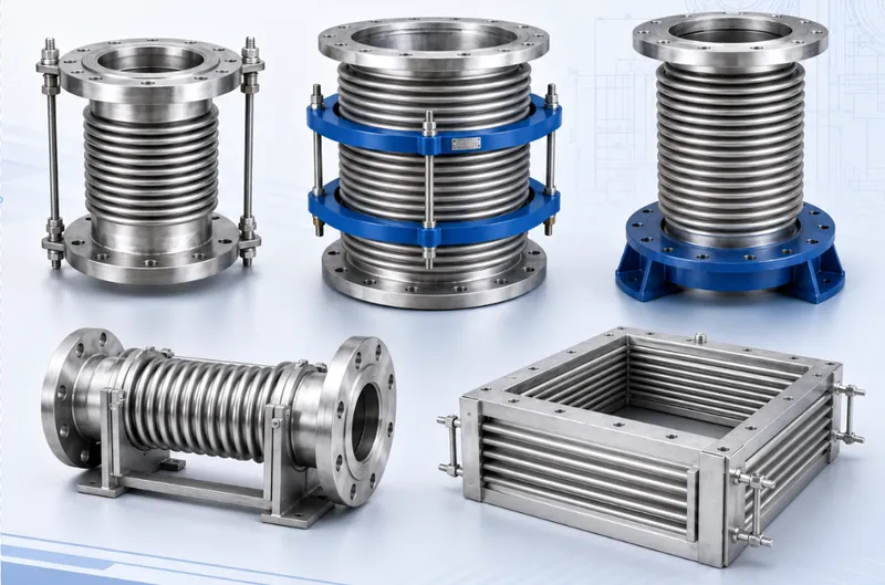
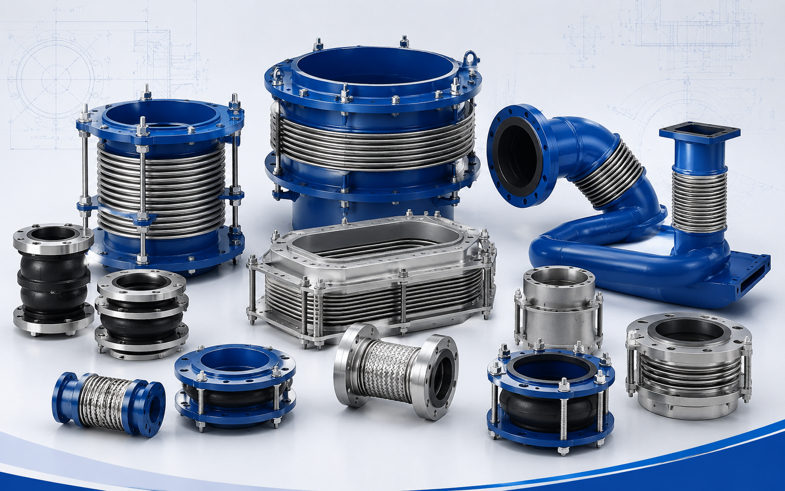
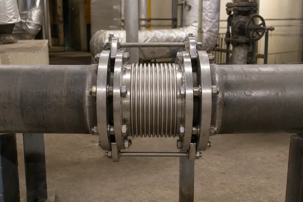
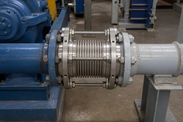
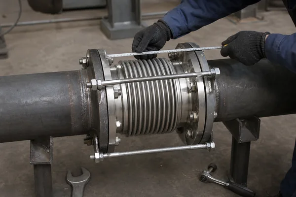
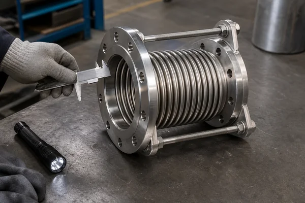
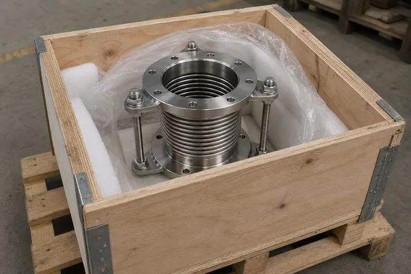
The following images support product identification, structure review, and purchasing communication. If the external rods are limit or transport protection parts, their final function should be confirmed by factory drawing.
A single axial metal bellows expansion joint is used in straight pipe runs where main anchors and pipe guides have already been considered. It absorbs compression or extension along the pipe axis. It is not a pressure-balanced joint and it is not the preferred solution for large lateral or angular movement. If the piping system has no reliable anchor points, the system design must be reviewed before selection.
Axial thermal movement compensation in straight runs of steam, hot water, heating and industrial process pipelines.
The pipe run should have main anchors, guides, confirmed installation length and a calculated movement value.
Long unanchored pipe runs, major lateral movement, or systems that require the joint itself to balance pressure thrust.
The standard single axial structure normally consists of one metal bellows element and two end connections. The bellows compresses or extends along the pipeline axis to absorb the length change caused by temperature variation. End connections may be flanged, welded or pipe-end type. Internal sleeves, external covers and shipping restraints are order-dependent and should not be described as standard unless confirmed.
When the pipe heats up, the straight run may push toward the expansion joint and compress the bellows. When the pipe cools or movement reverses, the bellows may extend. Pressure thrust is not cancelled by an single axial expansion joint with limit rods joint and must be resisted by the anchors.
Engineering note: local legacy images show external limit rods. If the rods are permanent limit or load-carrying parts, the product should be renamed and selected as a tied or limited design. If they are shipping restraints only, the installation instruction must confirm whether they are removed or retained.
Concentrates pipe length change in a calculated location and helps reduce thermal movement transmitted to pumps, valves, equipment nozzles or rigid connections.
The single-bellows construction is specified by size, pressure, temperature, movement and installation length, without mixing tied, hinged or pressure-balanced structures into this standard product.
Flanged ends support easier removal and replacement. Weld ends suit permanent pipeline connections. Sealing face, drilling, weld preparation and covers should follow the confirmed drawing.
| Size And Connection | DN / NPS, pipe outside diameter, installation length, flange standard, sealing face, bolt holes and weld-end dimensions. |
|---|---|
| Operating Conditions | Design pressure, working pressure, design temperature, working temperature, medium, corrosion condition, insulation and external environment. |
| Product Performance | Axial compression, axial extension, effective area, spring rate, fatigue-cycle requirement, internal sleeve and external cover. |
| Project Requirements | Anchor position, pipe-guide arrangement, equipment nozzle limits, installation direction, inspection standard, quantity, destination port and required documents. |
| Main Part | Selection Basis | Current Status |
|---|---|---|
| Metal bellows / body | Medium, temperature, pressure, corrosion and fatigue cycles | SS304 / 316L, final grade by order |
| End flanges or pipe ends | Pipeline standard, pressure class, sealing face and welding requirement | Stainless steel / carbon steel / alloy options, final material by order |
| Internal sleeve | Flow velocity, erosion, flow direction and pressure-drop concern | Optional; engineering confirmation required |
| External cover | Site protection, insulation, safety and transport protection | Optional; engineering confirmation required |
| Shipping bar or limit rod | Transport protection or special limit requirement | Local image conflict; manufacturer confirmation required |
| Nominal Size | 1.5 inch-155 inch (DN32-DN4000) | Nominal Pressure | 0.6 / 1.0 / 1.6 / 2.5 / 4.0 MPa |
|---|---|---|---|
| Compensation | 18-400 mm | Maximum Temperature | -40-450 °C |
| Connection Type | Flange, pipe | Flange Material | Stainless steel / carbon steel / alloy |
| Flange Standard | ANSI / DIN / EN / JIS | Body Material | SS304 / 316L |
Each pressure-rating column uses the format "axial compensation mm / spring rate N/mm". Detailed data above DN400 should be confirmed by drawing or manufacturer datasheet.
| DN | Corrugations | 0.25 MPa | 0.6 MPa | 1.0 MPa | 1.6 MPa | 2.5 MPa | Effective Area cm2 | Max. OD mm |
|---|---|---|---|---|---|---|---|---|
| 32 | 8 | 25 / 21 | 22 / 26 | 20 / 26 | 18 / 63 | 15 / 98 | 16 | 110 |
| 40 | 8 | 25 / 28 | 22 / 44 | 20 / 44 | 18 / 89 | 15 / 106 | 23 | 130 |
| 50 | 8 | 30 / 25 | 22 / 51 | 20 / 70 | 18 / 70 | 15 / 138 | 37 | 150 |
| 65 | 8 | 33 / 28 | 30 / 35 | 26 / 44 | 22 / 55 | 19 / 68 | 55 | 170 |
| 80 | 8 | 40 / 20 | 36 / 26 | 34 / 33 | 28 / 41 | 24 / 54 | 81 | 200 |
| 100 | 8 | 45 / 47 | 45 / 60 | 40 / 75 | 35 / 93 | 29 / 117 | 121 | 220 |
| 125 | 6 | 48 / 38 | 42 / 47 | 38 / 59 | 34 / 74 | 29 / 92 | 180 | 250 |
| 150 | 6 | 49 / 42 | 44 / 50 | 40 / 62 | 34 / 78 | 29 / 97 | 257 | 250 |
| 200 | 6 | 52 / 49 | 46 / 55 | 42 / 68 | 38 / 78 | 34 / 111 | 479 | 300 |
| 250 | 6 | 72 / 30 | 63 / 34 | 59 / 42 | 52 / 45 | 47 / 55 | 769 | 300 |
| 300 | 6 | 72 / 51 | 65 / 55 | 59 / 59 | 52 / 65 | 47 / 71 | 1105 | 340 |
| 350 | 6 | 72 / 58 | 65 / 62 | 59 / 67 | 52 / 74 | 47 / 81 | 1307 | 340 |
| 400 | 6 | 75 / 60 | 72 / 70 | 72 / 65 | 60 / 80 | 55 / 90 | 1430 | 380 |
Steam and condensate pipelines: installed in straight heated pipe runs to absorb axial thermal movement.
District heating and hot-water systems: used in heating networks, heat-exchange stations and long hot-water pipelines.
Chemical and industrial process lines: suitable for straight process piping with defined medium, temperature and pressure.
Pump-station or equipment-adjacent straight runs: absorbs axial thermal movement when allowed by engineering design.
Before installation, check the drawing, flow direction, installation length, end connection, anchor arrangement and guide arrangement. A single axial expansion joint does not act as the main anchor of the piping system and must not be installed in an unanchored run.
Check installation length, end dimensions, flange drilling, bellows appearance, surface protection and marking.
Check transition areas between bellows, end rings and pipe ends according to the order quality plan.
Confirm pressure, leakage, movement or action-related tests by project requirement; do not publish an unconfirmed test pressure.
Confirm end protection, shipping restraint, wooden case or pallet packing, documents and shipping marks.
DN / NPS, installation length, end connection, flange standard, bellows material, internal sleeve, external cover, surface treatment, packing and documents can be confirmed according to project data.
For quotation, please provide product name, pipe size, pressure, temperature, medium, axial movement, connection standard, installation length, material requirement, quantity, destination port and any drawing or site photo.
A standard single axial joint mainly absorbs axial compression and extension, and it does not balance pressure thrust. Tie rods or limit rods change the force boundary, so the product name and selection should be confirmed if permanent rods are present.
Its primary function is axial movement. If the pipeline has significant lateral movement, a universal, double-bellows or other engineered design is usually more appropriate.
In an single axial expansion joint with limit rods design, pressure thrust should be resisted by the main anchors and the piping system design, not by the bellows element itself.
Flanged ends are easier to remove and replace. Weld ends are suitable for permanent pipeline connections. Confirm pipeline standard, pressure class, sealing face, space and maintenance strategy.
Used when longer axial movement, stability or an external-pressure arrangement is required.
More suitable when lateral movement is the main requirement in the pipeline layout.
Considered when angular rotation and hinge-controlled load restraint are needed.
Considered where the piping system cannot accept high pressure thrust, with different space and cost implications.
Before ordering, confirm movement, pressure class, temperature, flange standard, material, and installation length instead of replacing only by appearance.
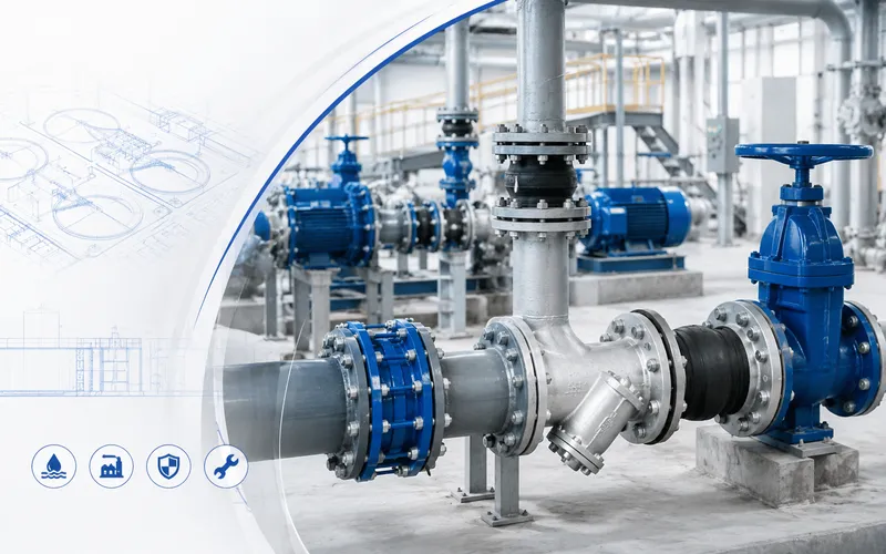
Application images show common installation positions. Final suitability depends on medium, pressure, temperature, pipeline movement, and support design.
Single axial metal bellows expansion joints are normally used with anchors and guides. Site installation should follow project drawings and instructions.
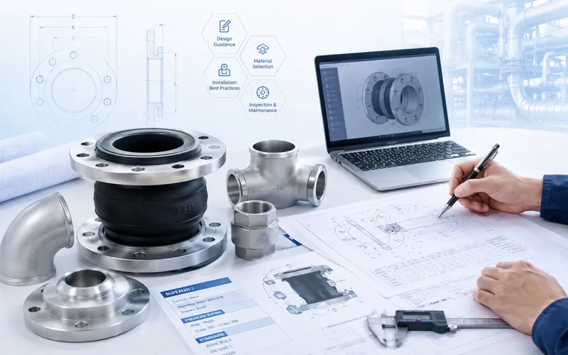
These images cover dimensional inspection and export packing. Pressure testing, material documents, certificates, and packing grade should be confirmed by order.
产品通过金属波纹管沿管道中心轴线的压缩与伸长吸收轴向位移,适用于运动方向明确的直线管段。


管道受热伸长或收缩时,波纹管通过轴向压缩或伸长吸收位移。管道运动应尽量沿产品中心轴线传递。
产品主要面向运动方向明确的直线管段,其使用效果同时取决于膨胀节结构、实际位移及管道系统条件。
由一个金属波纹管及两端连接件组成,主要用于吸收轴向压缩和轴向伸长。
配合适当的固定和导向结构,可将主要管道运动控制在产品中心轴线方向。
可根据管道标准、施工条件和维护要求选择法兰端、管端或定制连接结构。
尺寸、材料、位移能力、轴向刚度、附件和检验要求需根据实际工况确认。
| 公称直径范围 | DN32–DN4000 |
|---|---|
| 公称压力等级 | 0.25 / 0.6 / 1.0 / 1.6 / 2.5 / 4.0 MPa |
| 轴向补偿量 | 18–400 mm |
| 可选设计温度范围 | -40℃至450℃ |
| 连接形式 | 法兰端/管端,具体结构按确认图纸 |
| 法兰材料 | 不锈钢/碳钢/合金 |
| 法兰标准 | 可按 ASME、EN、DIN、JIS 等项目指定标准生产,具体标准号、压力等级及密封面形式按订单确认。 |
| 波纹管/主体材料 | 常用波纹管材料为 SS304、SS316L,其他材料可根据介质、设计温度、腐蚀条件及项目要求确认。 |
| 公称直径 DN | 波纹数量 | 公称压力等级(MPa) | 有效面积 cm² | 最大外径 mm | ||||
|---|---|---|---|---|---|---|---|---|
| 0.25 | 0.6 | 1.0 | 1.6 | 2.5 | ||||
| 32 | 8 | 25/21 | 22/26 | 20/26 | 18/63 | 15/98 | 16 | 110 |
| 40 | 8 | 25/28 | 22/44 | 20/44 | 18/89 | 15/106 | 23 | 130 |
| 50 | 8 | 30/25 | 22/51 | 20/70 | 18/70 | 15/138 | 37 | 150 |
| 65 | 8 | 33/28 | 30/35 | 26/44 | 22/55 | 19/68 | 55 | 170 |
| 80 | 8 | 40/20 | 36/26 | 34/33 | 28/41 | 24/54 | 81 | 200 |
| 100 | 8 | 45/47 | 45/60 | 40/75 | 35/93 | 29/117 | 121 | 220 |
| 125 | 6 | 48/38 | 42/47 | 38/59 | 34/74 | 29/92 | 180 | 250 |
| 150 | 6 | 49/42 | 44/50 | 40/62 | 34/78 | 29/97 | 257 | 250 |
| 200 | 6 | 52/49 | 46/55 | 42/68 | 38/78 | 34/111 | 479 | 300 |
| 250 | 6 | 72/30 | 63/34 | 59/42 | 52/45 | 47/55 | 769 | 300 |
| 300 | 6 | 72/51 | 65/55 | 59/59 | 52/65 | 47/71 | 1105 | 340 |
| 350 | 6 | 72/58 | 65/62 | 59/67 | 52/74 | 47/81 | 1307 | 340 |
| 400 | 6 | 75/60 | 72/70 | 72/65 | 60/80 | 55/90 | 1430 | 380 |
该产品主要用于能够通过固定和导向系统控制轴向运动的直线管段。具体适用性仍需结合介质、压力、温度、位移和管道受力条件确认。

用于工业供热、蒸汽、热水及换热系统直线管段的轴向热位移补偿。

适用于电厂及能源项目中具备合理固定、导向和支撑条件的辅助工艺管道。

用于经过介质、压力、温度、腐蚀条件和疲劳要求评审的工艺管线。

可用于重工业设施中的热力、工业气体及辅助工艺管线。
产品应安装在经过设计的管道系统中。安装前应核对产品状态、连接条件和管道布置,避免将安装误差、扭转载荷或其他非设计载荷传递给波纹管。

检查产品是否存在运输损伤,并核对连接方式、安装位置和安装空间。
不得通过强行压缩、拉伸或扭转膨胀节来修正管道安装误差。
应防止工具、吊具、焊渣、电弧及其他硬物损伤薄壁波纹管。
系统试验和投运前,应依据管道图纸检查固定、导向、支撑及连接状态。
实际检验项目应依据产品结构、订单要求和订单质量计划确定。不同订单的检测范围可能不同。

核查安装长度、连接尺寸、整体装配状态,并对关键连接部位和焊缝外观进行检查。

是否进行压力、密封或其他性能试验,应根据订单和产品要求确认。

对连接端、波纹管及附件进行适当保护,降低运输和装卸损伤风险。
Get professional solutions and competitive quotes from our engineering team.
Passen Sie Ihre Cookie-Präferenzen an. Notwendige Cookies sind immer aktiv.