 简体中文
简体中文  English
  日本語
日本語  한국어
한국어  Français
  Deutsch
  Español
  Português
  Русский
  العربية
  ไทย
ไทย  Tiếng Việt
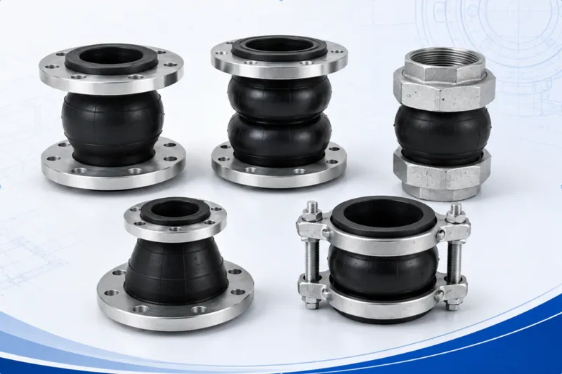

产品概述
PTFE-Lined Rubber Expansion Joint
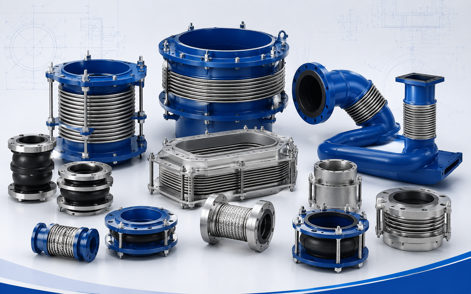
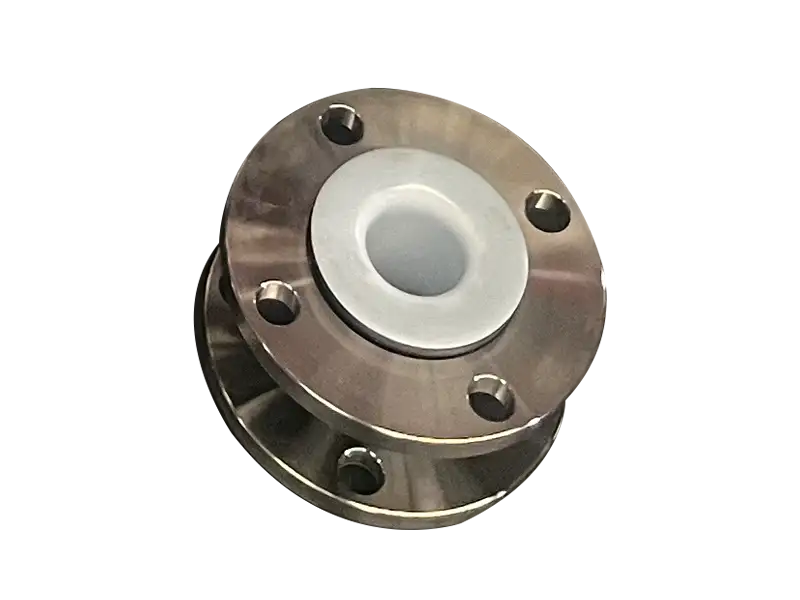
A PTFE-lined rubber expansion joint combines a fluoropolymer wetted barrier with a reinforced elastomeric flexible body.
The liner separates aggressive process media from the rubber carcass, while the elastomer and reinforcement provide flexibility and structural strength.
A Lined Rubber Joint, Not a Solid PTFE Bellows
In this construction, PTFE is used as the internal liner. It is not blended into the rubber, and the complete flexible body is not manufactured entirely from PTFE.
The fluoropolymer liner, rubber body, fabric reinforcement and metallic components perform different functions and must be evaluated as one assembly.
A white liner cannot be identified as PTFE from appearance alone. The actual polymer may be PTFE, FEP, PFA or another specified fluoroplastic and should be confirmed by documentation.
Continuity of the Wetted Surface
The liner should protect the internal bore and extend to the flange sealing areas according to the approved construction.
This arrangement reduces direct contact between the process medium and the elastomeric tube, metallic flange or liner termination.
The flared liner face can also form part of the flange seal. Whether a separate gasket is required depends on the specific design and installation instructions.
Chemical Resistance Requires Full Process Data
Fluoropolymers provide broad resistance to many aggressive chemicals, but product suitability still depends on chemical identity, concentration, temperature, pressure and exposure duration.
Mixtures, solvents, oxidizing chemicals, high-purity fluids and changing waste streams require more detailed review than a general description such as “acid” or “alkali.”
Compatibility of the liner, liner attachment, flange seal, rubber body and metallic parts should all be considered.
The Outer Elastomer Still Matters
Although the process medium is normally isolated from the rubber carcass, the outer elastomer remains exposed to ambient temperature, ozone, sunlight, oil mist and possible chemical splash.
Cover material and reinforcement should be selected for the external environment as well as mechanical loading.
If the fluoropolymer liner is damaged, process fluid may reach the underlying load-bearing construction.
The Liner Changes Flexibility
PTFE and rubber do not have the same extension and bending behavior.
Liner thickness, forming geometry and attachment to the elastomeric body can influence axial, lateral and angular movement capability.
Movement values from an unlined rubber joint should not automatically be used for the lined version.
Simultaneous movements must be assessed as a combined condition rather than treated as independent maximum values.
Flexible Equipment Connection
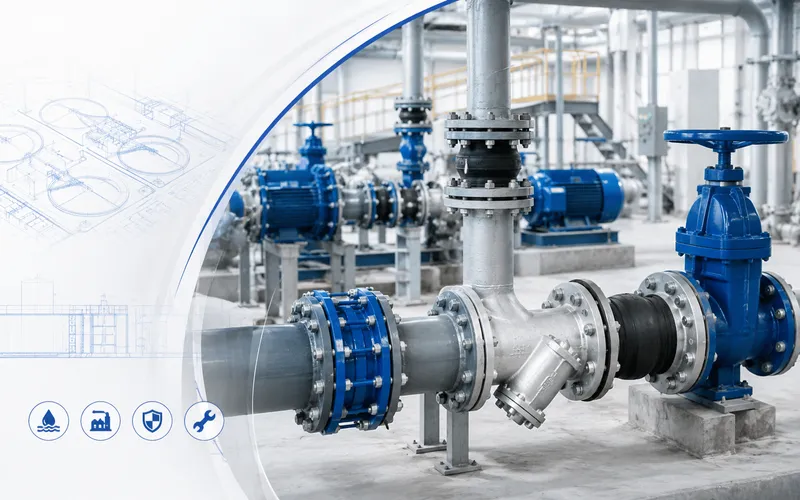
The joint can be used near pumps, valves, tanks, heat exchangers and chemical-processing equipment to accommodate approved movement and reduce part of the transmitted vibration.
It should not be forced into excessive compression, extension or lateral offset to correct poor pipe fabrication.
Permanent installation misalignment can concentrate load at the liner flare, arch roots and reinforced carcass.
Pressure Thrust Is Not Eliminated
Internal pressure acting over the effective joint area produces axial pressure thrust.
The fluoropolymer liner improves chemical isolation but does not restrain that force.
Anchors, equipment nozzles and control units must be reviewed for the complete piping load.
Control rods may be required where anchoring is limited, pressure fluctuates, nozzle loads are restricted or overextension must be prevented.
Vacuum Service Requires Specific Approval
Negative pressure can pull the liner and elastomeric body toward the flow passage.
Vacuum capability depends on size, temperature, liner attachment, arch construction and any internal vacuum support.
A PTFE material designation alone does not establish full-vacuum capability.
Design vacuum, operating vacuum and abnormal vacuum conditions should be stated separately.
Temperature Rating Belongs to the Complete Assembly
The maximum temperature cannot be selected from the fluoropolymer capability alone.
The elastomer, reinforcement, liner attachment, flange seal and pressure rating are also temperature dependent.
Allowable pressure or movement may need to be reduced as process temperature increases.
Protect the Flared Sealing Face
Before installation, the liner flare should be checked for flatness, folds, cuts, scratches and transport damage.
Mating flanges should be clean, flat and correctly aligned. Bolts should be tightened gradually in a cross pattern to avoid local overcompression.
Gasket selection and bolt loading must follow the approved instructions for the supplied construction.
Handling Restrictions
- Do not pry the liner with sharp tools
- Do not drag a rough flange across the sealing face
- Protect the liner from welding and grinding damage
- Do not twist the joint to align bolt holes
- Do not trap or fold the liner between flange faces
- Do not use an unapproved cleaning chemical
- Do not attempt an undocumented site repair
Typical Application Areas
- Acid, alkali and corrosive chemical transfer
- Chemical pump suction and discharge connections
- Storage tanks, reactors and heat exchangers
- Electroplating, pickling and surface-treatment lines
- Fine-chemical and industrial wastewater systems
- Selected processes sensitive to metallic contamination
- Equipment piping requiring corrosion resistance and flexibility
Avoid Universal Chemical-Resistance Claims
Hydrofluoric acid, strong oxidizers, hot solvents, mixed acids and high-purity processes can have special material and safety requirements.
Permeation, static control, cleanliness, regulatory compliance and leakage protection may also require project-specific review.
The joint should not be described as suitable for every chemical without a compatibility assessment.
Inspection Indicators
The liner flare should be inspected for wrinkling, discoloration, cracking, blistering or separation from the joint body.
The rubber arch should be checked for surface cracking, bulging, abnormal elongation, local collapse and exposed reinforcement.
Persistent flange leakage, loose liner areas, concentrated arch deformation or abnormal control-rod loading requires investigation.
Information Required for Quotation
- Complete chemical name, concentration and mixture ratio
- Presence of solids, crystals or abrasive particles
- Normal, maximum and minimum process temperature
- Design, operating and fluctuating pressure
- Design and abnormal vacuum conditions
- Pipe size and connection dimensions
- Flange standard, rating and facing
- Required axial, lateral and angular movement
- Whether movement components occur simultaneously
- Allowable pump or equipment-nozzle loads
- Anchor, guide and control-unit arrangement
- Required PTFE or alternative fluoropolymer grade
- Cleanliness, inspection and documentation requirements
Final liner material and attachment, elastomer and reinforcement construction, flange sealing arrangement, pressure-temperature range, vacuum capability, combined movement and control-unit configuration are subject to the approved technical specification, material certification and manufacturing drawing.
常见问题
Which media is PTFE-lined Flexible Rubber Coupling suitable for?⌄
How should EPDM, NBR or PTFE lining be selected?⌄
Are limit rods required?⌄
What should be noted during installation?⌄
What information is needed for a quotation?⌄
Can this product be customized by project drawing?⌄
What inspections are made before shipment?⌄
How are packing and export documents confirmed?⌄
Need the Right PTFE-lined Flexible Rubber Coupling for Your Project?
Get professional solutions and competitive quotes from our engineering team.