 简体中文
简体中文  English
  日本語
日本語  한국어
한국어  Français
  Deutsch
  Español
  Português
  Русский
  العربية
  ไทย
ไทย  Tiếng Việt

产品概述
Single Gimbal Expansion Joint Overview
A single gimbal expansion joint is a metal bellows assembly designed to accommodate angular rotation in multiple planes. It is used in industrial piping systems where movement is not restricted to one fixed plane.
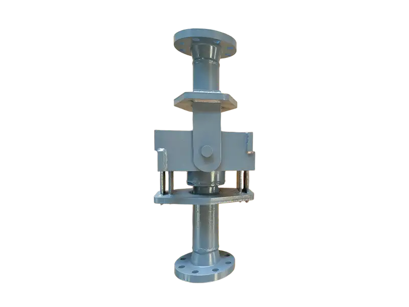
The assembly generally uses one metal bellows, two perpendicular pairs of hinge pins and a central gimbal ring. This arrangement allows the bellows to rotate about two different axes while controlling the direction of movement.
The gimbal hardware also restrains the pressure thrust generated by internal pressure acting on the effective area of the bellows. It limits unintended axial movement and helps protect the bellows from torsion.
Key Features
- Accommodates angular rotation in multiple planes
- Uses two perpendicular hinge axes and a central gimbal ring
- Gimbal hardware restrains internal pressure thrust
- Restricts unintended axial movement and bellows torsion
- Multiple joints can accommodate complex lateral movement
- Suitable for three-dimensional and complex piping layouts
- Reduces pressure thrust transmitted to external main anchors
- Available with welded, flanged or custom connection ends
- Engineered according to pressure, temperature and movement
Construction
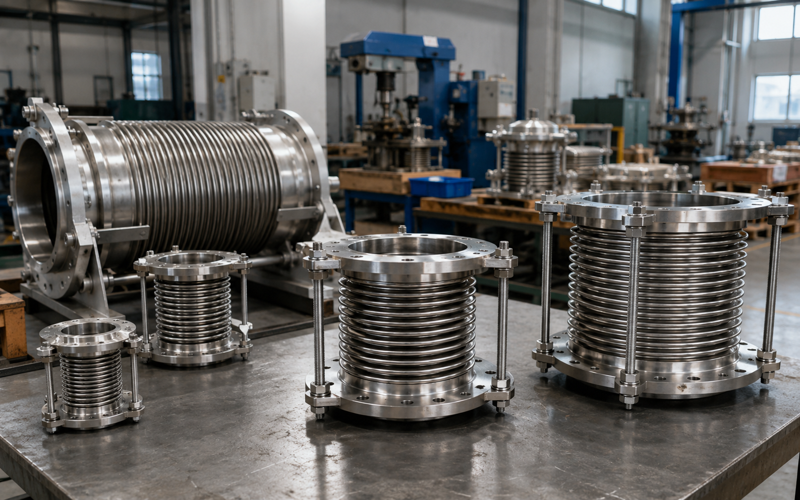
A single gimbal expansion joint generally consists of a metal bellows, pipe ends or connection flanges, a central gimbal ring, two sets of hinge plates, hinge pins, structural lugs and any required flow liner, external cover or shipping restraints.
The metal bellows is the flexible pressure-retaining element. The two perpendicular hinge axes determine the permitted angular degrees of freedom. The central gimbal ring connects the hinge sets and transfers pressure thrust, shear loads and selected external structural loads.
An internal flow liner may be incorporated for high-velocity, turbulent or particle-laden media.
Operating Principle
Thermal movement in a spatial piping system is converted through pipe bends and system geometry into angular rotation at the expansion joints.
Two perpendicular hinge sets allow the gimbal joint to rotate about different axes, enabling angular movement that is not limited to one fixed piping plane.
A single gimbal joint primarily accommodates angular rotation. It does not independently absorb large axial or lateral movement.
Two or more gimbal joints, or a combination of gimbal and hinged joints, can convert lateral and spatial pipeline displacement into angular rotation at several joint locations.
Difference from a Hinged Expansion Joint
A single hinged expansion joint has one hinge axis and permits angular rotation in one plane only.
A gimbal expansion joint has two perpendicular hinge axes connected through a central gimbal ring, allowing angular rotation in multiple planes. It is therefore more suitable for three-dimensional piping and complex movement directions.
Difference from a Universal Expansion Joint
A single gimbal expansion joint normally contains one metal bellows and uses gimbal hardware to provide multi-plane angular rotation.
A conventional universal expansion joint normally contains two bellows connected by an intermediate pipe and is primarily used to accommodate larger lateral movement. The two designs have different construction, movement capability and piping-layout requirements.
Movement Capability
A single gimbal expansion joint is primarily designed for angular rotation and should not be used as a conventional axial expansion joint.
In a multiple-joint system, lateral or spatial movement capacity depends on the allowable rotation, distance between rotation centers, pipe-leg length, piping geometry and support arrangement.
The joint should not be subjected to unapproved axial compression, extension, excessive lateral offset or torsional loading.
Pressure Thrust and Structural Loads
The gimbal hardware restrains the pressure thrust generated by internal pressure acting on the effective area of the bellows. This reduces the pressure load imposed on external main anchors.
The joint can still transmit angular spring force, shear force and selected structural loads to the adjoining piping system.
Pipe and medium weight, dynamic flow loads, wind, seismic effects and other external forces must still be considered in the piping design.
Anchors, Guides and Supports
Intermediate anchors, planar guides or other directional restraints may be required to maintain the intended piping geometry and movement path.
Pipe and medium weight should normally be carried by independent load-bearing supports. If the gimbal hardware is required to support pipe weight, wind, seismic or other external loads, those requirements must be identified during the design stage.
Material Selection
The bellows can be manufactured from project-confirmed stainless steels or corrosion-resistant alloys according to the medium, temperature, pressure and required fatigue life.
Pipe ends, flanges, gimbal rings, hinge plates, lugs and pins can be manufactured from carbon steel, stainless steel, alloy steel or other specified materials.
Gimbal-ring, pin and lug dimensions should be engineered according to pressure thrust, shear loading, external loads and the required structural safety margin.
Typical Applications
- Industrial steam and high-temperature hot-water piping
- Petrochemical and chemical process pipelines
- Power-generation, metallurgical and energy projects
- Three-dimensional and complex piping layouts
- Equipment nozzles and vessel connections
- High-temperature or higher-pressure industrial systems
- Piping requiring multi-plane angular movement
- Projects requiring restraint of pressure thrust
Installation Guidelines
- Confirm gimbal-ring orientation and intended rotation directions
- Verify face-to-face length, allowable angle and preset requirements
- Maintain proper alignment of connected piping
- Do not force the joint into position to correct piping errors
- Do not apply torsional loading to the metal bellows
- Do not remove permanent hinges, pins or gimbal components
- Provide anchors, guides and supports required by the piping design
- Protect the bellows and gimbal hardware during site welding
- Remove or adjust shipping restraints only as instructed
- Inspect pins, lugs, liners and movement clearance before operation
Operation and Inspection
The bellows, central gimbal ring, hinge plates, pins, lugs and connection welds should be inspected according to the medium, pressure, temperature, rotation cycles and maintenance plan.
Bellows distortion, pin wear, bent hinge plates, gimbal-ring misalignment, weld cracking, excessive rotation or interference between components should prompt a review of the actual movement, supports and piping geometry.
Quality and Inspection Options
Typical production checks can include material verification, visual inspection, critical dimensional inspection, bellows inspection, gimbal and hinge inspection, weld-area inspection and packaging inspection.
Pressure testing, leak testing, nondestructive examination, material certificates, dimensional reports or other project inspections can be agreed according to the purchase specification.
Information Required for Quotation
Please provide the following information so that the gimbal structure and compensation system can be properly evaluated:
- Nominal diameter or pipe outside diameter and wall thickness
- Design pressure and operating pressure
- Design, operating and installation temperatures
- Process medium and corrosion requirements
- Required angular rotation and movement directions
- Required lateral or spatial displacement
- Number of joints and distance between rotation centers
- Piping layout and installation position
- Weld-end, flange or other connection requirements
- Bellows and gimbal-hardware material requirements
- Pipe-weight or other external-load requirements
- Design cycles, inspection, packaging and quantity requirements
We can review and customize single gimbal expansion joints according to pressure, temperature, medium, movement direction, allowable rotation, piping layout and project drawings.
Final construction, materials, pressure rating, allowable rotation, movement capacity, structural loads and inspection requirements are subject to the approved technical specification and manufacturing drawing.
常见问题
What movement does Single-row Universal Joint Expansion Joint compensate?⌄
What is the purpose of a pressure-balanced design?⌄
How is bellows material selected?⌄
Are guides and anchors required?⌄
What information is needed for a quotation?⌄
Can this product be customized by project drawing?⌄
What inspections are made before shipment?⌄
How are packing and export documents confirmed?⌄
Need the Right Single-row Universal Joint Expansion Joint for Your Project?
Get professional solutions and competitive quotes from our engineering team.