 简体中文
简体中文  English
  日本語
日本語  한국어
한국어  Français
  Deutsch
  Español
  Português
  Русский
  العربية
  ไทย
ไทย  Tiếng Việt

产品概述
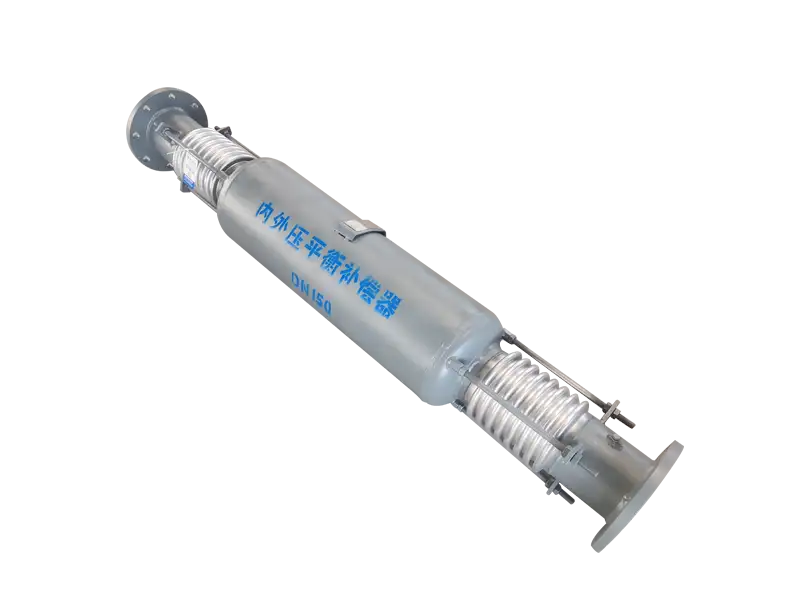
Combined Internal/External-Pressure Bypass Straight Pressure-Balanced Expansion Joint
This design combines two pressure conditions within one axial expansion-joint assembly. The working bellows accommodates thermal movement, while the balancing bellows develops an opposing pressure force through a bypass pressure path.
It is intended for straight piping where axial growth must be absorbed but full pressure thrust cannot be transferred to the main anchors or connected equipment.
Two Bellows, Different Pressure Conditions
The defining feature is that the working and balancing bellows do not operate under the same pressure arrangement.
The working bellows is normally pressurized internally and compresses or extends to accommodate axial pipeline movement.
The balancing bellows is supplied with pressure around its outside surface through a bypass or annular pressure passage.
Its effective area and load path are coordinated with the working section to develop an opposing axial force.
The Bypass Is a Pressure-Control Path
Process flow continues through the main flow section of the assembly, while system pressure is communicated to the balancing chamber through bypass openings or connecting passages.
The bypass does not function as a separate process pipeline. Its purpose is to deliver pressure to the correct side of the balancing bellows.
Passage size and chamber connection influence pressurization response, venting, drainage, pressure loss and sensitivity to deposits.
Where Axial Movement Occurs
As the connected straight pipe heats up, the working bellows compresses within its calculated travel.
During cooling, it extends in the opposite direction to accommodate pipe contraction.
The balancing bellows moves according to the internal design relationship, but its principal function is pressure-force balancing.
The assembly should therefore be selected primarily for axial movement, not for uncontrolled lateral, angular or torsional displacement.
How the Balancing Force Is Created
Line pressure acting on the effective area of the working bellows produces axial pressure thrust.
The same system pressure, applied to the appropriate effective area of the externally pressurized balancing bellows, produces a force in the opposite direction.
End plates, carrier structures, outer casings and permanent load-transfer components contain and transfer these forces within the expansion-joint assembly.
The resulting net pressure thrust transmitted to external piping is reduced according to the approved effective-area relationship.
Pressure Balance Is Not Zero System Load
The balancing principle addresses pressure thrust created by line pressure acting on bellows effective area.
Bellows spring forces, pipe and fluid weight, guide friction, dynamic flow forces and installation loads remain present.
Anchors, guides and load-bearing supports are still required according to the complete piping-system analysis.
Difference from a Fully Externally Pressurized Bypass Design
In a fully externally pressurized bypass design, both the working and balancing bellows are generally arranged to operate under external pressure.
That configuration places greater emphasis on externally pressurized bellows stability and large axial travel.
The combined internal/external-pressure design assigns different pressure conditions to the working and balancing sections, producing a different internal flow path, chamber layout and load relationship.
Difference from a Conventional In-Line Pressure-Balanced Joint
Conventional in-line pressure-balanced joints commonly use multiple internally pressurized bellows arranged along the pipeline axis.
The combined bypass design introduces a separate pressure path and an externally pressurized balancing section.
This changes the casing arrangement, chamber configuration, venting and drainage requirements and the way the balancing force is established.
Venting and Drainage Are Functional Requirements
Air trapped in the external balancing chamber can influence the pressurization process and dynamic response.
Steam, hot-water and condensing service also require evaluation of liquid accumulation, condensate corrosion and abnormal differential pressure.
Vent and drain connections must match the approved installation orientation and should not be plugged or modified without engineering review.
Differential Pressure Must Be Controlled
Correct balancing depends on pressure being communicated reliably from the main line to the balancing chamber.
A blocked bypass opening, trapped gas, accumulated deposits or an incorrectly isolated connection can create an unintended pressure difference.
Particle-laden, scaling or deposit-forming media require specific review of passage size, access and maintenance strategy.
Typical Project Conditions
- Straight steam piping with significant axial thermal growth
- District-heating and industrial hot-water networks
- Equipment connections with limited allowable nozzle loads
- Pipe racks where large pressure-thrust anchors are impractical
- Power, petrochemical and energy process lines
- Projects requiring a compact pressure-balancing arrangement
- Systems sensitive to pressure-thrust variation
Installation Focus
- Confirm process-flow direction and product orientation
- Identify bypass, vent and drain connection positions
- Verify the cold face-to-face length and preset condition
- Maintain accurate alignment of the connected piping
- Do not force the joint to correct construction errors
- Do not remove permanent balancing or load-transfer parts
- Protect bypass passages and chambers during site welding
- Confirm pressure passages are clear before commissioning
What to Monitor in Service
Inspection should include the bypass passages, pressure chambers, vent and drain connections as well as leakage and external deformation.
Abnormal travel, casing distortion, unusual noise, pressure fluctuation or unexpected nozzle loading may indicate that balancing pressure is not being established correctly.
The cause of a pressure imbalance should be identified before movement is restricted mechanically.
Engineering Data Required
- Piping layout and proposed installation location
- Nominal size, pipe outside diameter and wall thickness
- Design, operating and pressure-fluctuation range
- Design, operating and installation temperatures
- Process medium, phase, flow direction and corrosion conditions
- Required axial compression and extension
- Required operating cycles or design fatigue life
- Anchor and equipment-nozzle load limitations
- Available face-to-face and radial installation space
- Venting, drainage and blockage-prevention requirements
- Material, inspection and documentation requirements
Final pressure arrangement of the working and balancing bellows, effective-area relationship, bypass passages, axial movement, external connection loads and inspection requirements are subject to the approved calculations, technical specification and manufacturing drawing.
常见问题
What movement does Bypass-type Expansion Joint with Internal and External Pressure Balancing compensate?⌄
What is the purpose of a pressure-balanced design?⌄
How is bellows material selected?⌄
Are guides and anchors required?⌄
What information is needed for a quotation?⌄
Can this product be customized by project drawing?⌄
What inspections are made before shipment?⌄
How are packing and export documents confirmed?⌄
Need the Right Bypass-type Expansion Joint with Internal and External Pressure Balancing for Your Project?
Get professional solutions and competitive quotes from our engineering team.