 简体中文
简体中文  English
  日本語
日本語  한국어
한국어  Français
  Deutsch
  Español
  Português
  Русский
  العربية
  ไทย
ไทย  Tiếng Việt

产品概述
Elbow-Type Pressure-Balanced Expansion Joint
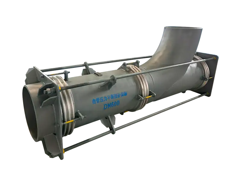
An elbow-type pressure-balanced expansion joint uses a change in pipeline direction as part of its pressure-balancing arrangement.
The line bellows is installed in the process-flow section, while a balancing bellows is positioned behind the elbow and connected through permanent structural hardware.
The Elbow Is Part of the Force-Balancing System
The elbow does more than redirect process flow. It provides the geometry required to position the balancing bellows opposite the pressure thrust generated at the working section.
This arrangement is particularly useful near pumps, compressors, turbines, heat exchangers, vessels and other load-sensitive equipment.
Line Bellows and Balancing Bellows
The line bellows is located in the process-flow path and accommodates the specified pipeline movement.
The balancing bellows is arranged behind the elbow and designed with an effective area coordinated with the working section.
When the line bellows compresses, the balancing bellows moves in the opposite direction according to the structural relationship.
Containing Pressure Thrust
Process pressure acting on the effective area of the line bellows produces axial pressure thrust.
Pressure acting on the balancing bellows develops an opposing force. Tie rods, carrier rings, end plates and the elbow structure connect the two force systems.
Most of the pressure thrust is therefore contained within the assembly rather than transferred directly to adjacent equipment or main anchors.
Bellows spring forces, support friction, dead weight and other piping loads remain and must be included in the system analysis.
Axial and Universal Variants
A basic elbow pressure-balanced design generally uses one line bellows and one balancing bellows and is intended mainly for axial movement.
A universal flow section can use two line bellows separated by a center spool, together with the balancing bellows. This configuration can be designed for axial and lateral movement.
Lateral capability must be confirmed from the number and arrangement of the line bellows. It should not be assumed from the product name alone.
Only very limited angular movement should be considered unless it is specifically included in the design.
Where This Design Adds Value
- Equipment nozzles with limited allowable loads
- Pipe sections that already require a change in direction
- Pump and compressor suction or discharge piping
- Steam turbine and heat-exchanger connections
- Locations where large pressure-thrust anchors are impractical
- Process lines requiring movement and nozzle-load control
Tie Rods Are Permanent Load-Carrying Parts
The tie rods are normally part of the permanent pressure-thrust load path. They are not ordinary shipping restraints.
Rod quantity, diameter, material, nut position and attachment geometry are selected from the calculated pressure and structural loads.
Removing rods or changing nut positions can disturb the balancing relationship and should not be done without approval.
Supporting the Asymmetrical Assembly
The elbow, balancing bellows and rear structural section create an asymmetrical assembly with a specific center of gravity.
Suitable load-bearing supports should carry the dead weight without preventing the required movement of either bellows section.
Equipment nozzles and thin-wall bellows should not be used to support the complete assembly weight.
Use Near Rotating Equipment
A conventional unrestrained axial joint installed close to rotating equipment can transmit substantial pressure thrust to the equipment nozzle.
The elbow pressure-balanced arrangement reduces that pressure load, leaving spring force, weight and other residual piping forces to be checked against the allowable nozzle loads.
Flow Liner Considerations
High-velocity, turbulent or particle-laden media may require internal flow liners.
Liner direction must match process flow, and sufficient operating clearance must be provided for the specified movement.
Bidirectional flow, reverse purging, solids deposition and elbow erosion should be identified before design.
Installation Orientation
- Confirm inlet, outlet and process-flow direction
- Position the balancing bellows as shown on the approved drawing
- Verify the cold position of both bellows sections
- Do not rotate the assembly into another elbow orientation
- Do not force the joint to correct piping misalignment
- Do not remove permanent tie rods or carrier structures
- Provide suitable support for the elbow and balancing section
- Protect bellows and structural hardware during site welding
In-Service Inspection
Inspection should include the line bellows, balancing bellows, tie rods and rear carrier structure.
The two bellows sections should move according to their intended relationship. Movement at the line bellows without corresponding balancing movement requires investigation.
Bent rods, loose nuts, carrier-ring deformation, assembly sagging or excessive movement at one bellows may indicate incorrect support, orientation or piping displacement.
Engineering Information Required
- Complete piping layout and elbow orientation
- Location relative to connected equipment
- Required axial and any lateral movement
- Design, operating and fluctuating pressure
- Design, operating and installation temperatures
- Process medium, phase, flow direction and velocity
- Allowable equipment-nozzle forces and moments
- Anchor, guide and load-bearing support conditions
- Available face-to-face and balancing-section space
- End connections, materials and inspection requirements
Final line-bellows arrangement, balancing-bellows effective area, elbow orientation, tie-rod loads, movement capacity, nozzle loads and support requirements are subject to the approved calculations, technical specification and manufacturing drawing.
常见问题
What movement does Bend-Type Pressure-Compensated Expansion Joint compensate?⌄
What is the purpose of a pressure-balanced design?⌄
How is bellows material selected?⌄
Are guides and anchors required?⌄
What information is needed for a quotation?⌄
Can this product be customized by project drawing?⌄
What inspections are made before shipment?⌄
How are packing and export documents confirmed?⌄
Need the Right Bend-Type Pressure-Compensated Expansion Joint for Your Project?
Get professional solutions and competitive quotes from our engineering team.