 简体中文
简体中文  English
  日本語
日本語  한국어
한국어  Français
  Deutsch
  Español
  Português
  Русский
  العربية
  ไทย
ไทย  Tiếng Việt

产品概述
Rectangular Metal Bellows Expansion Joint
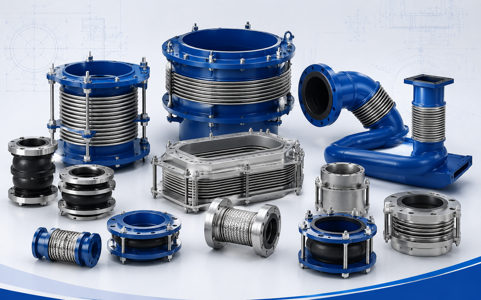
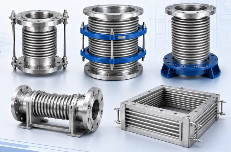
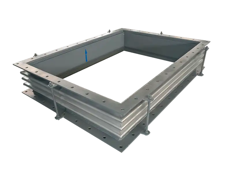
A rectangular metal bellows expansion joint matches the cross-section of a rectangular duct, flue or equipment connection.
The assembly normally consists of rectangular metallic bellows, connecting frames, engineered corner sections and an optional internal flow liner.
It is not simply a circular bellows reshaped into a rectangle. The long sides, short sides, corners, frame stiffness and duct loading require a dedicated project design.
The Duct Shape Influences the Entire Design
A circular pipe distributes pressure loading relatively evenly around its circumference.
A rectangular duct contains broad flat panels and four corner transitions, so its long and short sides can deform differently.
Even a comparatively low pressure difference can create a substantial total force when acting across a large rectangular area.
Bellows flexibility, frame stiffness, corner stress, duct reinforcement and external restraints must therefore be reviewed together.
Corner Geometry Is a Critical Feature
The four corners connect the individual bellows sides into one continuous sealed structure.
Depending on dimensions and movement, the design can use single-mitre, double-mitre, rounded or other approved corner arrangements.
Corner geometry influences bellows forming, weld location, deformation distribution and fatigue performance.
It should not be altered during fabrication or site installation without engineering review.
Single Units Mainly Accommodate Axial Movement
A conventional single rectangular expansion joint primarily accommodates thermal movement along the duct centerline.
As the adjoining duct expands, all four bellows sides compress together. During cooling, the bellows move in the opposite direction.
A calculated amount of lateral or angular flexibility may be available, but construction misalignment should not be treated as continuous operating movement.
Significant Lateral Travel Usually Requires Two Bellows
Where the project requires substantial lateral movement, a universal rectangular arrangement can use two bellows sections separated by a center frame or duct spool.
Coordinated angular deformation at the two flexible sections allows the center section to translate laterally.
Center-section length affects lateral movement capacity, assembly weight, installation envelope and support requirements.
Combined Movements Require Combined Evaluation
Axial, lateral and angular movements use the same flexible bellows capacity.
When more than one movement occurs, the complete hot-to-cold displacement path must be evaluated.
Maximum movement values in different directions should not be added independently.
Duct twist, racking or diamond-shaped distortion is normally outside the intended movement of a standard rectangular unit.
Positive Pressure and Vacuum Create Different Risks
Positive internal pressure tends to expand the bellows and load the connecting frames outward.
Vacuum or negative pressure can pull thin surfaces inward and may cause bellows instability, frame distortion or duct-panel deflection.
The maximum positive pressure, maximum negative pressure and expected pressure fluctuations should be stated separately.
The Bellows Must Not Carry Duct Weight
Adjoining ductwork, insulation, dampers, valves and equipment accessories should be supported independently.
Dead weight transferred into the joint can continuously compress the lower bellows, stretch the upper bellows and create uneven corner loading.
Supports should carry weight and control the duct position without preventing the specified movement.
Frame Stiffness Maintains the Rectangular Geometry
The connection frames must maintain their approved shape during transport, lifting, installation and operation.
Inadequate stiffness can lead to long-side bowing, unequal diagonal dimensions, uneven sealing faces or localized bellows deformation.
Large units can require stiffeners, temporary transport bars and purpose-designed lifting points.
Internal Liners Protect the Bellows
High-velocity flue gas, dust-laden flow or abrasive service may require an internal flow liner.
The liner smooths the internal passage, reduces direct impingement on the bellows and corners, and can reduce turbulence within the convolution space.
Liner overlap normally has a defined flow direction and should prevent process material from entering the protected cavity.
Thermal expansion gaps and movement clearances must prevent liner contact, buckling or restriction at operating temperature.
High-Temperature Ducts May Need Thermal Protection
Where the process gas is hot but the bellows or external frame must operate at a lower temperature, the design can incorporate liners, insulation fill or a thermal-barrier system.
Thermal protection must consider expansion, shrinkage, fibre erosion, thermal bridging and maintenance access.
Insulation must not fill the bellows movement space or block liner clearances.
This Is Not a General Vibration Isolator
A rectangular metallic joint can accommodate an approved amount of dynamic duct displacement, but it does not replace fan balancing, foundation isolation or structural duct reinforcement.
Continuous high-frequency vibration can add fatigue loading at bellows roots and corner welds.
Known vibration frequency, amplitude and operating conditions should be submitted for application review.
Large Units Can Be Supplied in Sections
Units exceeding transport or lifting limitations can be engineered as several sections for site assembly.
Section joints, site welds, liner connections and the installation sequence must be established before manufacturing.
Site assembly directly affects leak tightness, diagonal dimensions and bellows movement and should follow the approved procedure.
Shipping Bars Must Be Identified Correctly
Large rectangular joints commonly include temporary bars to protect the frames during transport and handling.
Some bars must be removed after installation, while other external components may be permanent guides or limit devices.
Their function should be confirmed from the manufacturing drawing rather than appearance alone.
Typical Applications
- Boiler inlet and outlet flue ducts
- Air preheater and economizer connections
- Flue-gas desulphurization and denitrification systems
- Dust-collection and industrial exhaust ducting
- Furnaces, incinerators and heat-treatment equipment
- Steel, cement, metallurgical and chemical plants
- Turbine and large-equipment exhaust systems
Check Both Diagonals Before Installation
The duct opening should be checked for width, height, flange flatness and both diagonal dimensions.
Unequal diagonals can force the joint into a pre-racked diamond shape, creating additional load at the corners and long bellows sides.
Bolts, jacks or the bellows itself should not be used to force distorted duct openings together.
Installation and Welding Controls
- Confirm flow direction, orientation and cold length
- Check duct width, height and diagonal dimensions
- Keep the end frames parallel and free from racking
- Verify any specified cold preset or pre-compression
- Do not place lifting slings directly on the bellows
- Do not weld temporary attachments to the convolutions
- Protect thin bellows from spatter, grinding and impact
- Remove shipping restraints only as instructed
- Confirm that the liner can move without interference
Inspection Should Include All Four Corners
Inspection should confirm that the four bellows sides are moving in a reasonably coordinated manner.
Corner areas should be checked for cracking, abnormal folding, leakage traces and localized overheating.
Frame bowing, changing diagonal dimensions, loose liner sections and abnormal support displacement should also be investigated.
Movement concentrated on only one side can indicate duct sagging, non-parallel interfaces, restrained supports or a movement direction different from design.
Engineering Data Required
- Clear duct width, height and detailed interface drawing
- Flanged-frame or weld-in connection dimensions
- Maximum positive and negative design pressure
- Design, operating and excursion temperatures
- Process gas composition, flow direction and velocity
- Dust concentration and abrasion conditions
- Axial, horizontal, vertical and angular movement
- Combined movement sequence
- Duct support, hanger and stiffener arrangement
- Available face-to-face length and external clearance
- Flow-liner, wear-protection and insulation requirements
- Transport restrictions and site-assembly conditions
- Material, welding, inspection and documentation requirements
Final bellows construction, corner arrangement, frame stiffness, movement capacity, pressure or vacuum loading, flow liner, thermal protection and sectional delivery plan are subject to the approved technical specification, design calculations and manufacturing drawing.
常见问题
What movement does Metal Expansion Joint compensate?⌄
What is the purpose of a pressure-balanced design?⌄
How is bellows material selected?⌄
Are guides and anchors required?⌄
What information is needed for a quotation?⌄
Can this product be customized by project drawing?⌄
What inspections are made before shipment?⌄
How are packing and export documents confirmed?⌄
Need the Right Rectangular Metal Bellows Expansion Joint for Your Project?
Get professional solutions and competitive quotes from our engineering team.