 简体中文
简体中文  English
  日本語
日本語  한국어
한국어  Français
  Deutsch
  Español
  Português
  Русский
  العربية
  ไทย
ไทย  Tiếng Việt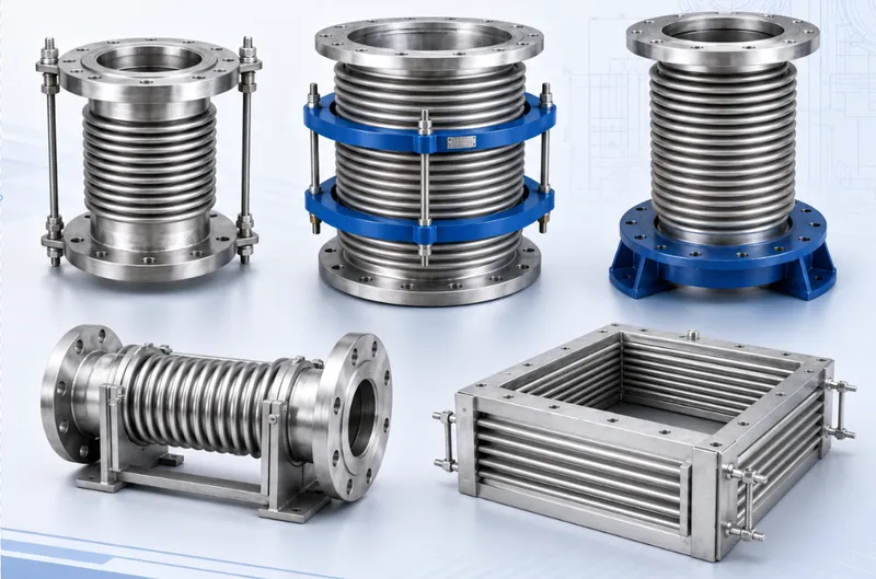

Product Overview
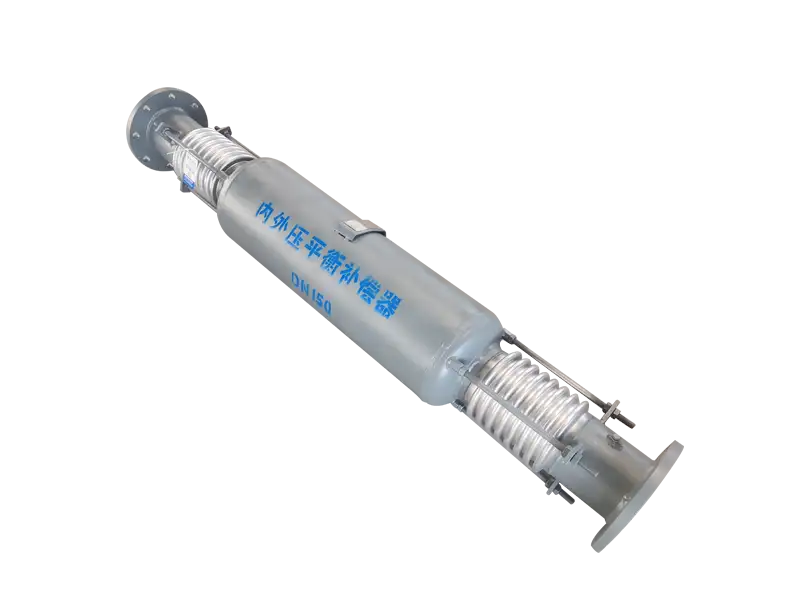
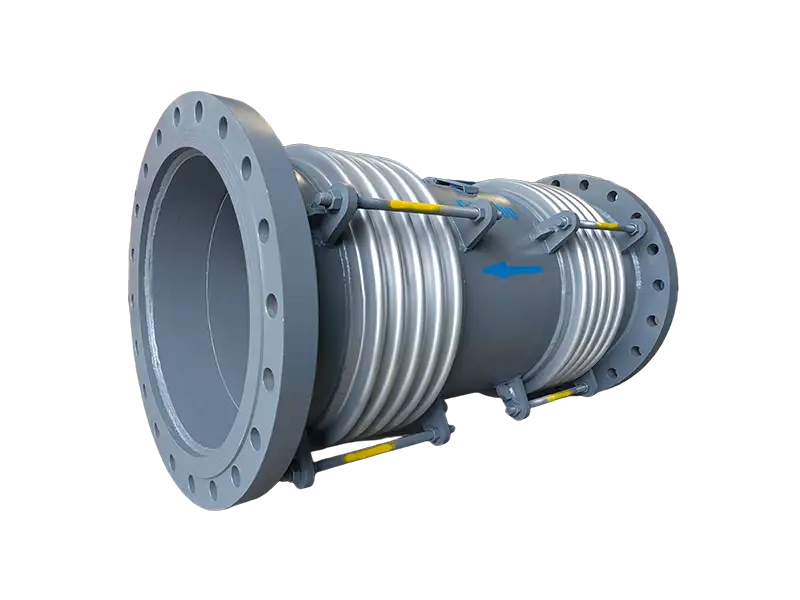
Tied Universal Expansion Joint
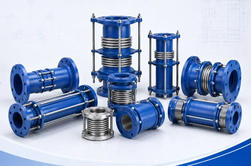
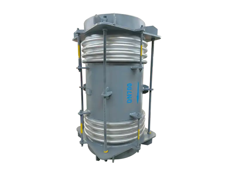
A tied universal expansion joint uses two flexible bellows elements to create lateral movement within a restrained assembly.
Permanent tie rods connect the end structures, control the overall length and provide a load path for internal pressure thrust.
The Tie Rods Are Structural Components
The rods are not temporary shipping restraints. They remain in service and carry the axial force generated when process pressure acts on the effective bellows area.
Because the overall length is restrained, the standard tied universal joint is generally not free to absorb axial pipeline movement. Its principal function is lateral displacement.
Rod quantity, diameter, material and attachment geometry must be selected from pressure thrust, structural loading and the required movement arrangement.
How Lateral Travel Is Developed
When the piping shifts laterally, the two bellows rotate in opposite directions. Their combined angular deformation allows the intermediate pipe to translate relative to the connection ends.
The bellows are not intended to be pulled directly sideways. Lateral travel is created by controlled rotation at two flexible centers.
A longer distance between those centers can provide greater lateral movement for the same bellows rotation, but also increases overall length, weight and installation-space requirements.
Defined-Plane Movement
A conventional tie-rod arrangement normally directs lateral movement within one specified plane.
A specially designed two-rod configuration can also permit limited angular movement in that same plane, but this capability must be stated in the approved manufacturing drawing.
Multi-plane movement generally requires gimbal hardware or another purpose-designed restraint arrangement.
Difference from an Untied Universal Joint
Both designs contain two bellows separated by an intermediate pipe and can accommodate lateral movement.
An untied universal joint does not contain permanent hardware that restrains pressure thrust. External main anchors normally carry that load.
The tied design restrains overall length and contains pressure thrust through rods and structural end components.
Rod Nuts and Operating Clearance
Rod-nut position and clearance depend on the intended movement and structural load path.
Some designs require the nuts to remain continuously engaged, while selected arrangements require calculated clearance for angular rotation.
Site personnel should not tighten, loosen or reposition the nuts without the approved installation instructions. An incorrect adjustment can change movement capacity and bellows loading.
Typical Service Locations
- Steam piping with defined lateral thermal movement
- Hot-water, heating and circulation systems
- Connections between heat exchangers and main piping
- Petrochemical and chemical process lines
- Power-plant, boiler and energy piping
- Locations requiring restraint of pressure thrust
- Pipe sections with adequate space for a universal assembly
Intermediate-Pipe Weight
The intermediate pipe establishes the distance between the two rotation centers, but also adds dead weight to the assembly.
Long or large-diameter horizontal units should be evaluated for center-spool sag and continuous lateral loading on the bellows.
Where support is required, it must carry weight without preventing the specified lateral movement.
Internal Liner Clearance
High-velocity, turbulent or particle-laden media may require an internal liner to protect the bellows.
The liner requires sufficient overlap and radial clearance for the full lateral travel. Inadequate clearance can cause contact, noise, wear or movement restriction.
Bidirectional flow, reverse purging and solids accumulation should be identified before the liner arrangement is finalized.
Installation Restrictions
- Do not remove permanent tie rods or load-bearing nuts
- Do not use the rods to pull misaligned flanges together
- Do not axially stretch the joint to correct pipe length
- Do not twist the assembly to align flange holes
- Do not exceed the approved preset lateral offset
- Provide clearance for the intermediate pipe and liner
- Support pipe and valve weight independently
Service Inspection
The two bellows should share the lateral movement in the manner anticipated by the design.
Inspection should check for uneven bellows rotation, bent rods, loose nuts, intermediate-pipe sagging and liner contact.
Excessive movement at one bellows or movement outside the specified plane may indicate incorrect guiding, preset direction or piping displacement.
Engineering Data Required
- Piping layout and joint orientation
- Required lateral movement and movement plane
- Nominal size or pipe outside diameter and wall thickness
- Design, operating and test pressure
- Design, operating and installation temperatures
- Process medium, flow direction, velocity and corrosion conditions
- Available face-to-face length and lateral clearance
- Intermediate-pipe weight and support conditions
- End connections, materials, cycle life and inspection requirements
Final tie-rod quantity and arrangement, center-spool length, bellows rotation, lateral movement capacity, spring forces and structural loads are subject to the approved calculations, technical specification and manufacturing drawing.
Frequently Asked Questions
What movement does Double-rod Expansion Joint compensate?⌄
What is the purpose of a pressure-balanced design?⌄
How is bellows material selected?⌄
Are guides and anchors required?⌄
What information is needed for a quotation?⌄
Can this product be customized by project drawing?⌄
What inspections are made before shipment?⌄
How are packing and export documents confirmed?⌄
Need the Right Tied Universal Expansion Joint for Your Project?
Get professional solutions and competitive quotes from our engineering team.