 简体中文
简体中文  English
  日本語
日本語  한국어
한국어  Français
  Deutsch
  Español
  Português
  Русский
  العربية
  ไทย
ไทย  Tiếng Việt
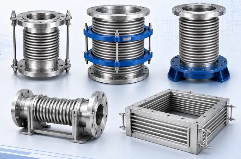
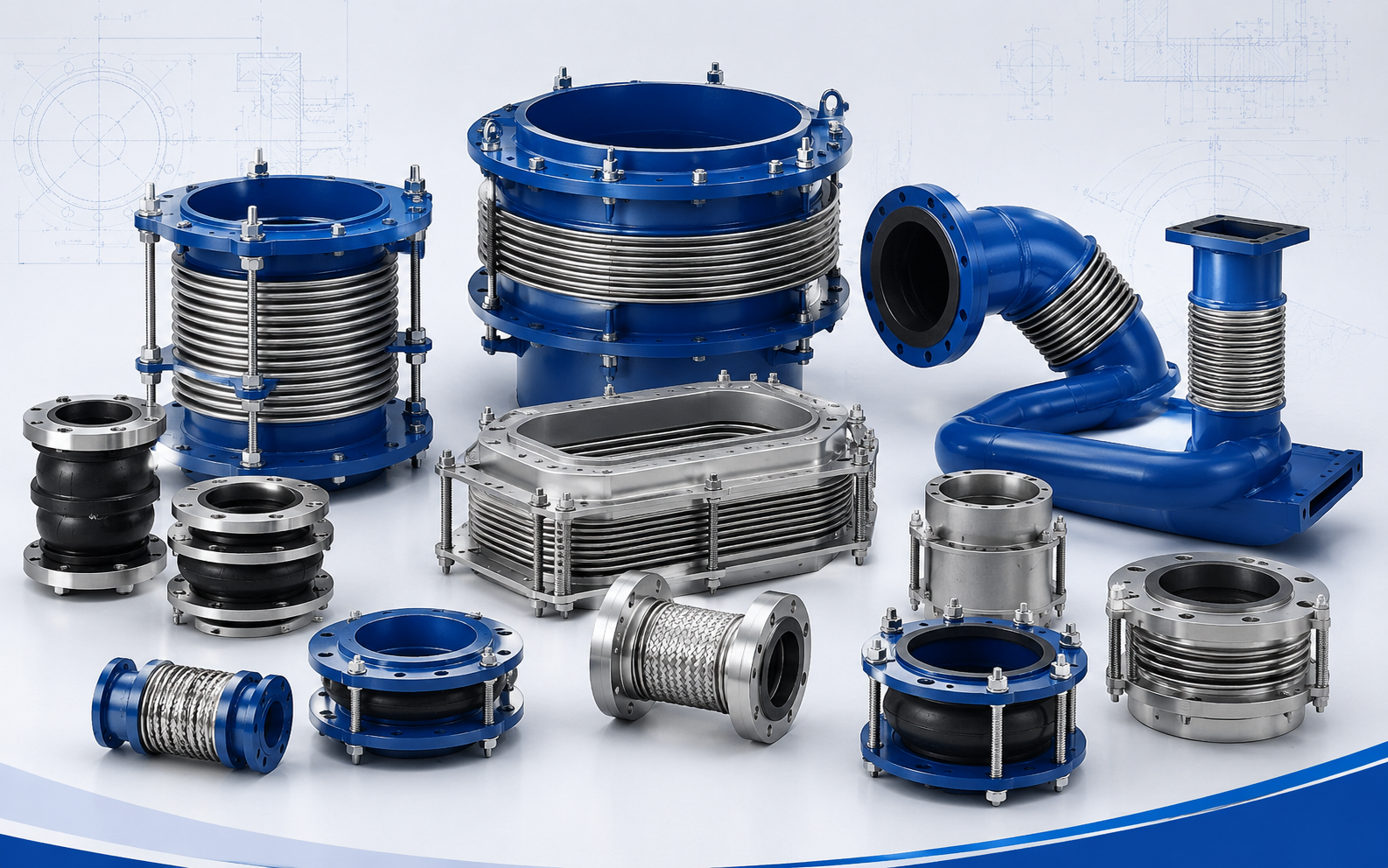

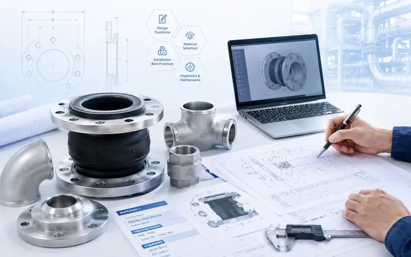
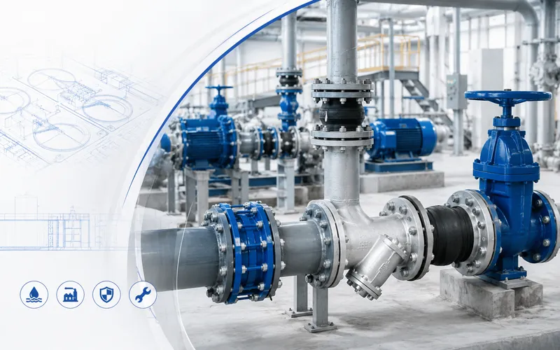
产品概述
Tied Universal Gimbal Expansion Joint
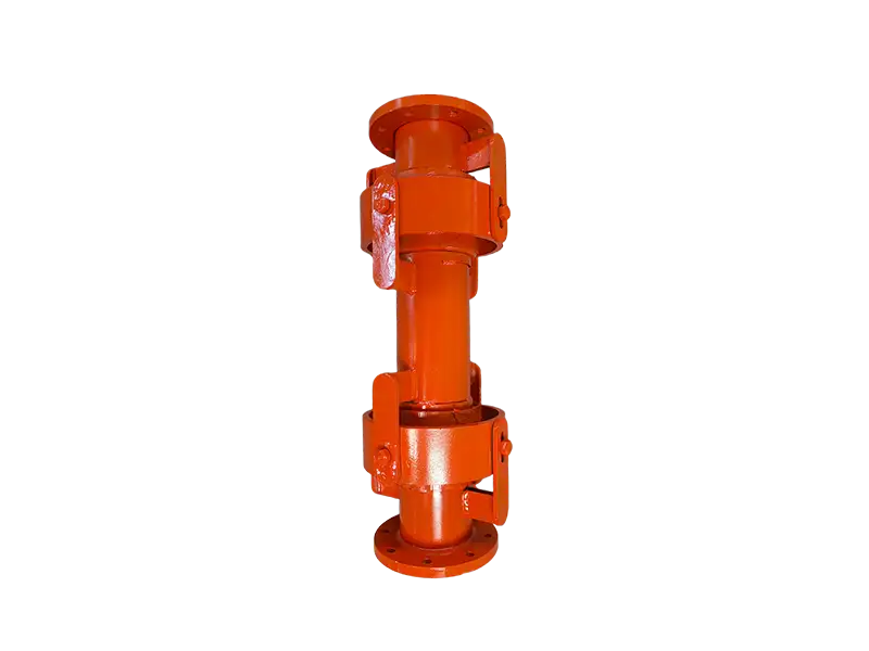
A tied universal gimbal expansion joint is a complete spatial movement system, rather than two ordinary bellows placed in the same assembly.
Two gimbaled bellows units are separated by an intermediate pipe. Angular rotation at each end allows the intermediate pipe to translate, producing lateral displacement of the assembly.
Movement Geometry
When the connected piping moves laterally, each bellows rotates through a controlled angle. The combined angular movement shifts the intermediate pipe relative to the two connection ends.
The lateral displacement is therefore developed through bellows rotation and geometric offset, rather than by directly shearing or pulling a single bellows sideways.
For a given allowable bellows rotation, increasing the distance between the two rotation centers can provide greater lateral movement capacity.
The resulting increase in overall length, weight and installation envelope must also be considered.
Dual Gimbal Hardware
Each end of the assembly incorporates a gimbal ring, hinge plates, pins and structural lugs.
The two perpendicular rotational axes in each gimbal permit angular movement in more than one plane.
Using gimbal hardware at both bellows enables the complete joint to accommodate lateral displacement whose direction is not limited to a single piping plane.
Role of the Intermediate Pipe
The intermediate pipe establishes the lever distance between the two flexible rotation centers.
Its length directly influences required bellows rotation, available lateral movement and the overall dimensions of the assembly.
It is therefore an engineered component and should not be shortened, extended or replaced at site without design approval.
Pressure-Thrust Restraint
Internal pressure acting on the effective bellows area generates axial pressure thrust.
The gimbal rings, hinge plates, pins and structural lugs provide a permanent load path that restrains this thrust within the assembly.
This reduces pressure thrust transmitted to external anchor points. The hardware must therefore remain complete and correctly assembled.
Pressure-thrust restraint does not mean that the expansion joint should support pipe weight, equipment weight or unapproved external bending loads.
Difference from a Single Gimbal Joint
A single gimbal expansion joint contains one bellows and primarily provides angular rotation in multiple planes.
The tied universal gimbal design contains two gimbaled bellows and an intermediate pipe. Their combined rotation produces useful lateral movement within one assembly.
Difference from an Untied Universal Joint
An untied universal expansion joint also contains two bellows and an intermediate pipe, but it does not necessarily include hardware capable of restraining pressure thrust.
The tied universal gimbal joint adds load-carrying gimbal structures that control movement and contain pressure thrust.
This makes it suitable for large-diameter, higher-pressure or nozzle-load-sensitive piping systems.
Movement Boundaries
The main function of this design is lateral movement and approved angular rotation.
The gimbal hardware normally restrains unrestricted axial extension or compression. Axial thermal growth should therefore not be added directly to the specified lateral movement requirement.
The assembly must not be subjected to torsion around the pipe centerline.
Where the Design Is Most Useful
- Three-dimensional high-temperature piping
- Pipelines with lateral movement in changing directions
- Connections between vessels, exchangers and process equipment
- Large-diameter steam and hot-gas piping
- Petrochemical, power and metallurgical process lines
- Locations where pressure thrust at anchors must be limited
- Long pipe spans requiring substantial lateral movement
Support Strategy
Pipe guides and load-bearing supports should direct movement into the intended gimbal rotations and prevent uncontrolled axial motion or torsion.
Pipe and process-medium weight should be carried by external supports.
For long horizontal assemblies, the weight of the intermediate pipe and its effect on the gimbal hardware should be evaluated during design.
Internal Liner Arrangement
High-velocity, turbulent or particle-laden service may require an internal flow liner to protect the bellows and provide a smoother flow path.
Because relative lateral movement occurs between the two ends, liners require sufficient overlap and operating clearance.
Bidirectional flow, reverse purging and solids accumulation should be identified before the liner is designed.
Installation Checks
- Verify the orientation of both gimbal assemblies
- Confirm the cold face-to-face length and preset offset
- Provide full lateral clearance for the intermediate pipe
- Do not remove permanent rings, pins, hinges or structural lugs
- Do not twist the joint to align flange holes
- Do not force the assembly to correct piping errors
- Protect bellows and pin surfaces during site welding
- Handle temporary shipping restraints as instructed
What to Inspect in Service
Inspection should compare the angular movement of the two bellows and confirm that movement is being shared as intended.
Uneven bellows deformation, worn pins, bent hinge plates, intermediate-pipe sagging or liner interference may indicate incorrect movement, inadequate support or installation misalignment.
Engineering Data Required
This expansion joint must be selected from the complete piping geometry. Nominal diameter and pressure alone are not sufficient for design.
- Piping layout and proposed joint location
- Required lateral movement and movement direction
- Any simultaneous angular rotation
- Design and operating pressure
- Design, operating and installation temperatures
- Process medium, flow direction and velocity
- Available face-to-face and lateral clearance
- Pipeline and intermediate-pipe support conditions
- Flanged, welded or other connection requirements
- Material, cycle-life and inspection requirements
Final bellows rotation, intermediate-pipe length, gimbal dimensions, lateral movement, structural loads and material selection are subject to the approved calculations, technical specification and manufacturing drawing.
常见问题
What movement does Double-row Universal Joint-type Expansion Joint compensate?⌄
What is the purpose of a pressure-balanced design?⌄
How is bellows material selected?⌄
Are guides and anchors required?⌄
What information is needed for a quotation?⌄
Can this product be customized by project drawing?⌄
What inspections are made before shipment?⌄
How are packing and export documents confirmed?⌄
Need the Right Double Gimbal Expansion Joint for Your Project?
Get professional solutions and competitive quotes from our engineering team.