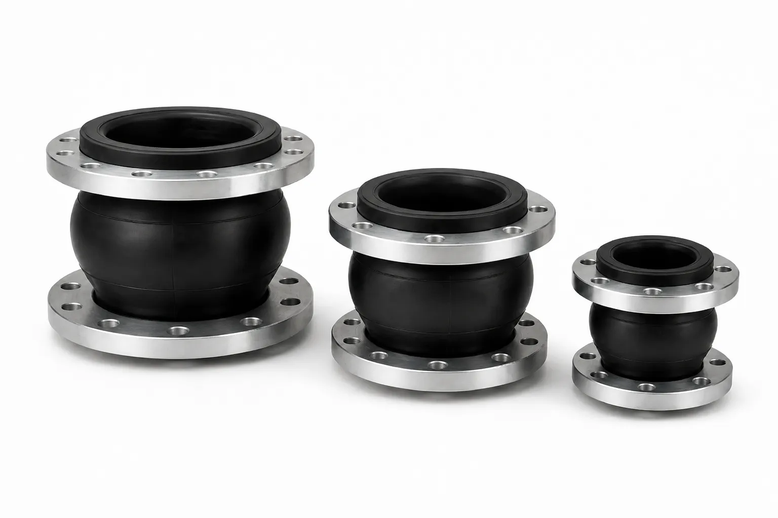
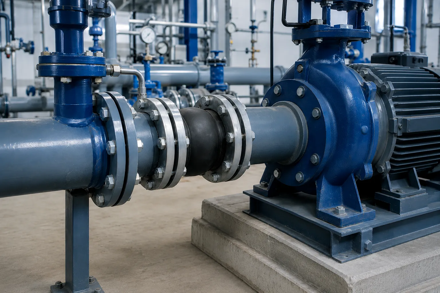
Rubber expansion joints on pump suction lines provide a flexible connection, absorb limited movement and isolate some mechanical vibration. Unlike a discharge line, a suction line can operate below atmospheric pressure during startup, at low water level or during flow fluctuation. When that happens, atmospheric pressure pushes the rubber arch inward, which can cause inward collapse or instability. This article helps contractors, engineers and procurement teams understand where the vacuum risk comes from, what to check before selecting a suction-side joint, and which installation checks prevent misalignment and premature failure. Final suitability must be confirmed against approved drawings, datasheets, quotations and contract documents.
Why a Pump Suction Line Is Not a Normal Positive-Pressure Line
A normal positive-pressure line keeps its internal pressure above atmospheric pressure, so the rubber arch mainly resists internal pressure that pushes outward. A pump suction line can fall below atmospheric pressure, which means the joint must also resist external pressure pushing the arch inward. The two cases load the joint in opposite directions.
Positive-pressure selection focuses on working pressure, test pressure and temperature. Suction-side selection must also cover the minimum internal pressure, the expected vacuum level and how the arch behaves under negative pressure. Do not copy a discharge-side selection simply because the pump station is the same.
Pressure direction and loading
Under positive pressure the arch bulges outward and the reinforcement carries internal pressure. Under vacuum the arch is pushed inward and the reinforcement plus the arch profile must resist external pressure. A product safe under positive pressure is not automatically safe under vacuum.
Why positive-pressure data alone is not enough
If the buyer only supplies a pressure rating without a vacuum condition, the supplier cannot judge whether the arch will collapse. Describe the suction side and the discharge side separately and state the pressure condition of each.
How Vacuum Forms on the Suction Side
Vacuum risk on the suction side comes from several sources: pump startup before a stable flow is established, a water level below the pump centerline that increases the suction lift, long or undersized suction piping, blocked strainers or filters, and flow fluctuation or cavitation that drops local pressure. Any of these can push the suction-side pressure below atmospheric pressure.
Startup and low-water-level conditions
During startup the suction pressure drops briefly, and a continuously low water level keeps the suction lift high, holding the joint under negative pressure for long periods.
Increased resistance and cavitation risk
A blocked strainer, a partially closed valve or excessive bends increase resistance and lower suction pressure. During cavitation the local pressure falls below the vapour pressure of the liquid and the pressure fluctuation is severe, affecting both the impeller and the joint.
What Negative Pressure Does to a Rubber Arch
Under vacuum, atmospheric pressure pushes the rubber arch inward. If the reinforcement cannot resist the external pressure, the arch may deform inward, develop folds or become unstable. Inward deformation reduces the flow area, increases local resistance and creates stress concentrations where the arch folds.
Instability usually appears as surface collapse, asymmetric deformation or the reinforcement layers pressing together. This changes the intended movement capability and accelerates rubber fatigue. The deeper and more frequent the negative-pressure duty, the higher the risk.
How to detect inward deformation in service
Inspect the arch through a sight glass or transparent section while running to see whether the surface caves in, folds permanently or deforms asymmetrically; after shutdown, check whether the arch recovers its shape. If deformation is visible, stop and verify the actual pressure condition instead of continuing to run.
Why wall thickness alone is not the answer
Arch wall thickness, reinforcement structure, ply count and arch profile together determine vacuum resistance. Adding outer rubber thickness by itself does not reliably resist negative pressure; the vacuum capability must be confirmed from the product datasheet against the design duty.
Why Sphere Count Alone Does Not Define Vacuum Capability
Single sphere and double sphere describe the construction and flexibility of the joint, not its vacuum capability. Either design may be built with vacuum support or reinforcement, and either may lack it. The ability to resist vacuum depends on the design parameters, not on the name.
| Comparison | Single sphere joint | Double sphere joint |
|---|---|---|
| Construction | One arch | Two arches |
| Installed length | Shorter face-to-face length | Longer face-to-face length |
| Flexibility | Lower movement capacity | Higher movement capacity |
| Vacuum capability | Design-dependent; name alone is not proof | Design-dependent; name alone is not proof |
Judge vacuum capability from the vacuum or negative-pressure condition stated in the product datasheet and compare it with the actual minimum internal pressure. Name, photo or sphere count cannot replace that confirmation, and no vacuum rating can be assumed without it.
Vacuum information to confirm during selection
- Minimum internal pressure or vacuum level on the suction line;
- Duration and frequency of the negative-pressure duty;
- Maximum permitted inward deformation of the arch;
- Whether vacuum support or reinforced construction is required.
When Vacuum Support or Reinforced Construction Is Required
When the suction side operates at or below atmospheric pressure continuously or frequently, and the standard construction cannot resist the external pressure, vacuum support must be evaluated. Vacuum support uses a support ring, internal stiffening or a special reinforcement layer to help the arch resist inward deformation.
Signals that vacuum support needs evaluation
- The suction line operates below atmospheric pressure for long periods;
- The pump starts frequently and negative pressure appears at every start;
- The water level fluctuates and the suction lift changes often;
- Past projects showed arch collapse or instability.
Confirmation boundary for vacuum support
Whether vacuum support is required and which form it takes must be confirmed by the supplier against the actual duty, product construction and design verification. After support is added, the installed length and movement capability may change, so the installation conditions must be re-checked.
Supporting the Pump, Pipework and Valves Independently
A suction-side rubber expansion joint provides a flexible connection only. It does not carry the weight of the pump, the pipework or the valves. Provide independent support for the pump, pipework and valves; the joint does not carry weight and must never be used as a load-bearing element or to absorb large alignment errors.
Common support mistakes
- Hanging pipe weight from the rubber expansion joint;
- Using the joint to absorb large pump-to-pipe misalignment;
- Letting valve weight rest on the joint flanges;
- Installing without fixed or guided supports nearby.
Correct support arrangement
Place supports near the pump flanges to carry the weight, install fixed and guided supports on the pipework as designed, and support valves separately. The suction line should impose minimal additional load on the pump flanges; the joint only provides the flexible connection and limited movement.
Alignment and Natural Installed Length
Before installation, check the alignment between the pump suction flange and the pipe flange. The flange faces must be parallel and coaxial and the bolt holes must line up. Never stretch, compress or twist a rubber expansion joint to compensate for misalignment, and do not force the joint into position when the flange spacing does not match.
Alignment checks
- Flange face parallelism and coaxiality;
- Flange spacing matching the natural installed length;
- Bolt hole positions matching the flange standard;
- Sealing faces clean and undamaged.
Why natural installed length matters
Natural installed length is the face-to-face distance of the joint without external force. The joint should remain within the design installed-length range after installation; going outside the range changes the movement allowance and can affect sealing performance.
RFQ Data for a Suction-Side Rubber Expansion Joint
When requesting a quotation for a suction-side rubber expansion joint, provide complete duty data. The minimum internal pressure and vacuum condition are the items most often omitted. Complete data lets the supplier judge the construction and propose the correct configuration.
RFQ checklist
| Item | Information to provide |
|---|---|
| Nominal size | DN or actual pipe size |
| Pressure | Working pressure, minimum internal pressure or vacuum level |
| Medium | Medium name, concentration and solid content |
| Temperature | Medium temperature and maximum ambient temperature |
| Flange | Flange standard, rating and facing type |
| Installed length | Face-to-face distance and permitted movement values |
| Location | Suction or discharge side, pump type and duty |
How medium and temperature affect the construction
The inner rubber layer is selected for media compatibility, while the outer rubber layer handles weathering and the external environment. Medium, temperature and negative pressure together determine the reinforcement, flanges and arch structure; never select on a single parameter.
What a Rubber Expansion Joint Cannot Replace
A suction-side rubber expansion joint is one flexible component in the system. It cannot replace fixed pipe supports, guides, anchoring design or overall piping stress analysis as part of the system engineering. Vacuum risk, cavitation, water hammer and pipe vibration must be solved by system design, not by using the joint as a corrective tool.
Where the joint applies
Rubber expansion joints are suitable for flexible connection, limited movement compensation and a degree of vibration isolation, provided the system supports and alignment meet the design requirements. Duty outside the permitted movement, pressure or vacuum range is not covered by the product scope.
What the joint cannot do
- It cannot replace fixed and guided supports;
- It cannot stop cavitation or water hammer;
- It cannot correct severe initial misalignment;
- It cannot act as a sealing remedy for a vacuum system.
Suction-Side Installation Inspection Checklist
Inspect before, during and after installation, checking flanges, supports, alignment and operating conditions step by step. Use the checklist below so that installation errors do not cause premature joint failure.
Pre-installation checks
- Verify the product model and specification match the order;
- Check the arch surface for damage, folds or foreign material;
- Confirm the flange standard and rating match the pipework;
- Confirm vacuum support has been configured for the duty.
During and after installation
- Align the flange faces and keep the spacing at natural installed length;
- Tighten bolts evenly in a symmetrical sequence;
- Do not stretch, compress or twist the joint;
- Support the pump, pipework and valves independently;
- Check the arch for inward deformation, folds or leaks after trial running.
Get Selection Support for Your Suction Line
When you need a rubber expansion joint for a pump suction line, send the nominal size, pressure and minimum internal pressure or vacuum level, medium, temperature, flange standard, installed length, movement and installation location. The engineering support team will confirm the construction, reinforcement and whether vacuum support is required.
For a suction-line joint, the engineering review covers the minimum internal pressure, medium, temperature, flange standard, installed length, movement and support arrangement, and verifies whether vacuum support is required. Submit the duty data through the contact form or send the pump datasheet to our engineering team, and the final configuration will be confirmed against approved drawings, datasheets, quotations, purchase orders and contract documents.