 简体中文
简体中文  English
  日本語
日本語  한국어
한국어  Français
  Deutsch
  Español
  Português
  Русский
  العربية
  ไทย
ไทย  Tiếng Việt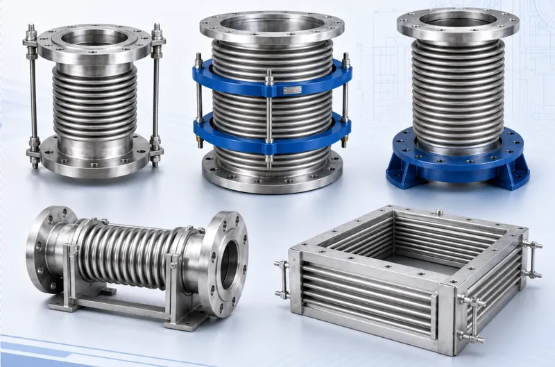
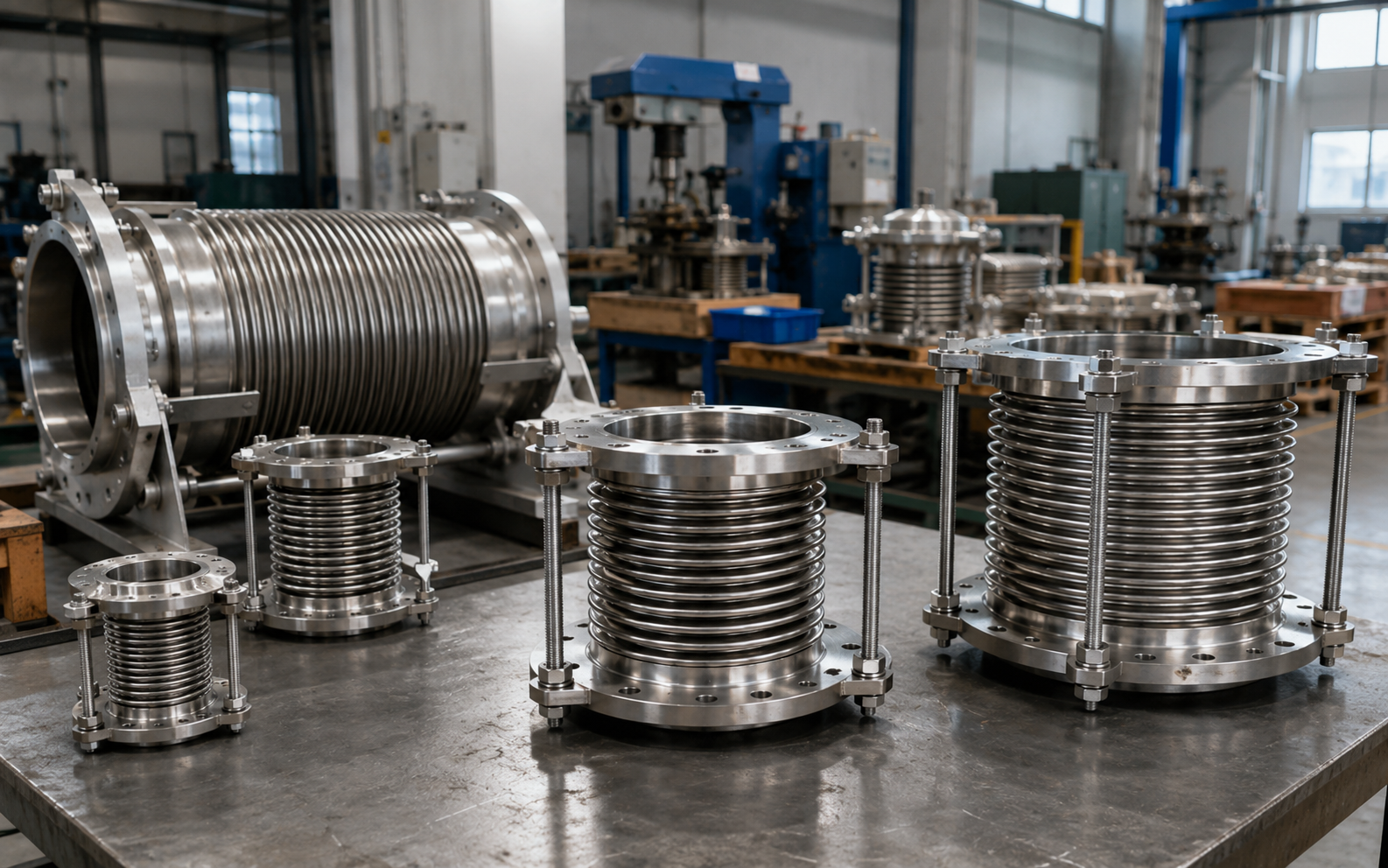
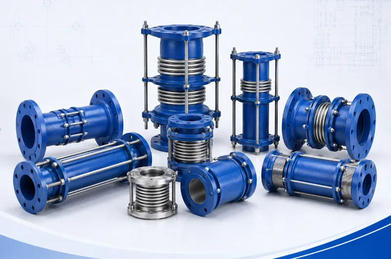
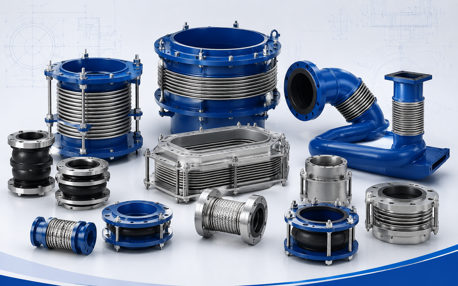

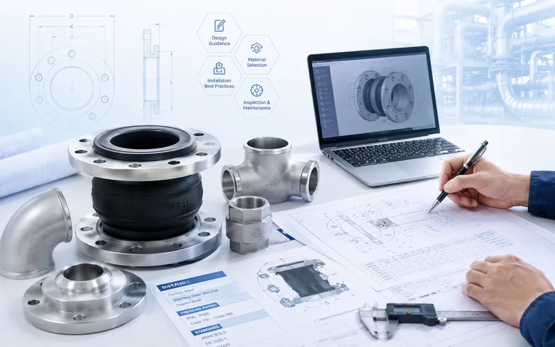
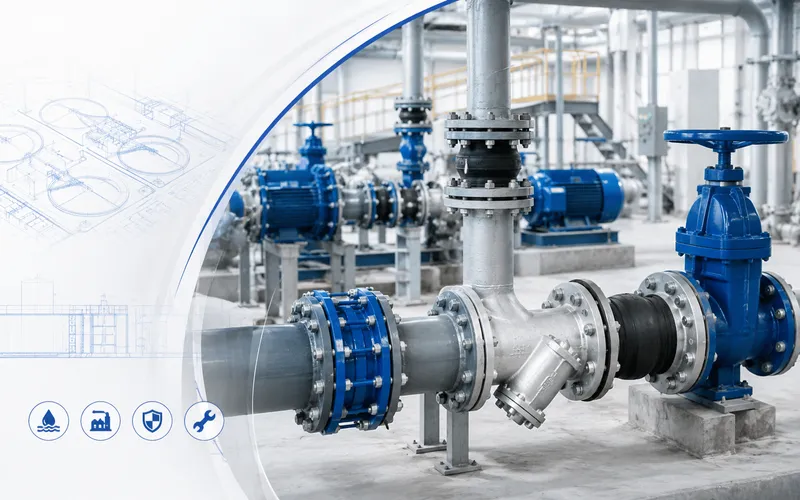
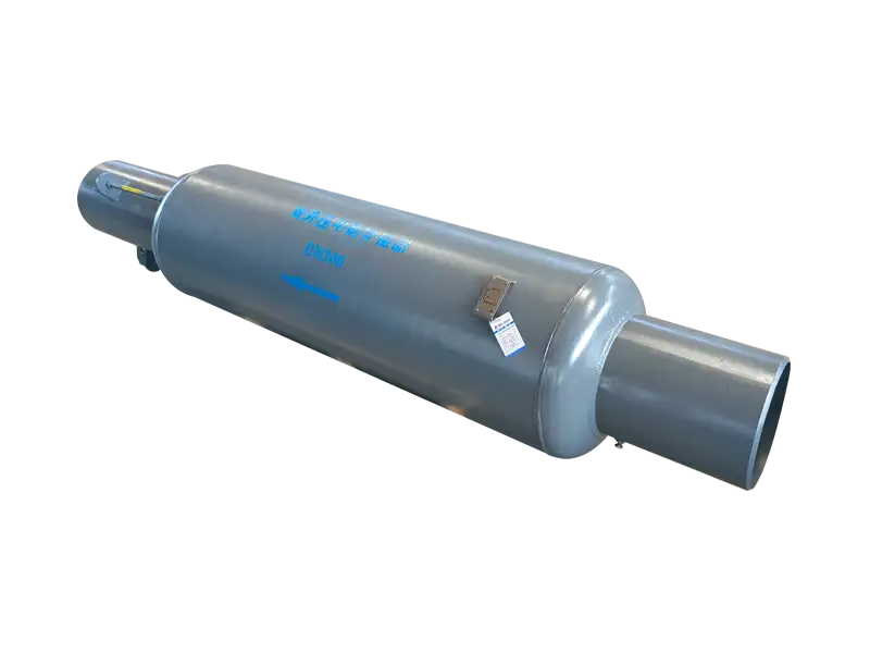
Full Externally Pressurized Bypass Straight Pressure-Balanced Expansion Joint
Product Overview
Full Externally Pressurized Bypass Straight Pressure-Balanced Expansion Joint
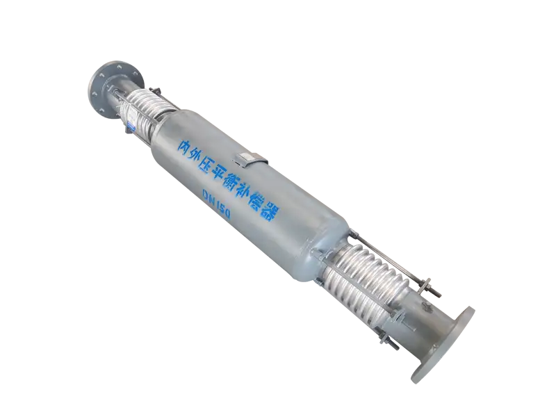
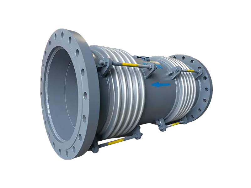
A full externally pressurized bypass straight pressure-balanced expansion joint is a metal bellows assembly designed to accommodate axial thermal movement in straight piping while reducing pressure thrust transmitted to external main anchors and equipment nozzles.
The process medium is routed through bypass or annular passages into external pressure chambers surrounding the working and balancing bellows.
The working bellows accommodates axial compression and extension, while the balancing bellows and internal load-transfer components generate an opposing pressure force within the assembly.
The externally pressurized construction supports axial bellows stability and can be engineered for relatively large axial movement.
Key Features
- Accommodates axial compression and axial extension
- Working and balancing bellows operate under external pressure
- Supports improved axial stability of the bellows
- Suitable for relatively large axial movement requirements
- Internal balancing structure reduces pipeline pressure thrust
- Helps reduce pressure load on anchors and equipment nozzles
- External casing provides mechanical protection for the bellows
- Available with welded, flanged or custom connection ends
- Engineered according to operating conditions and project drawings
Construction
The assembly generally consists of inlet and outlet pipe ends, a working bellows, a balancing bellows, an external casing, an internal guide or flow pipe, bypass openings or annular passages, end rings, structural load-transfer components and any required vent, drain or shipping-restraint parts.
The working bellows is the primary flexible element for accommodating axial thermal movement. The balancing bellows is coordinated with the effective area of the working bellows to create an opposing pressure force.
The external casing, end rings and internal structural components form the required pressure chambers and load-transfer path. They also provide selected mechanical protection for the bellows during handling and installation.
The exact number of bellows, bypass arrangement, internal guiding system and structural configuration should follow the approved sectional and manufacturing drawings.
Operating Principle
As the connected pipeline heats up, the pipe section expands axially and the working bellows compresses within its engineered movement range.
As the pipeline cools, the working bellows extends in the opposite direction, accommodating contraction of the pipe section.
The process medium enters the pressure chamber outside the bellows through bypass openings, an internal flow pipe or an annular passage. Pressure therefore acts on the outer surfaces of the working and balancing bellows.
The effective areas, spring characteristics and internal load path are coordinated so that pressure forces acting in opposite directions are generated within the assembly.
End rings, structural plates, rods or other load-carrying components transfer these forces internally, reducing net pressure thrust transmitted to the external piping and connected equipment.
Externally Pressurized Bellows
Internally pressurized bellows can be subject to radial expansion and column instability, particularly where a long bellows section or large axial movement is required.
Applying process pressure to the outside of the bellows supports axial stability and provides additional design flexibility for a greater number of convolutions and relatively large axial movement.
External pressurization does not provide unlimited movement capacity. Actual movement depends on bellows material, convolution geometry, number of convolutions, number of plies, pressure, temperature, spring rate, stability and required fatigue life.
Pressure-Balancing Function
A conventional unrestrained axial expansion joint generates axial pressure thrust when process pressure acts on the effective area of the bellows. That thrust normally has to be resisted by a main anchor.
In this pressure-balanced arrangement, the working and balancing bellows are designed with coordinated effective areas. Internal pressure creates forces of similar magnitude acting in opposite axial directions.
The balancing forces are transferred through the structural components inside the assembly, reducing the net pressure thrust transmitted to main anchors and equipment nozzles.
Pressure balancing does not eliminate bellows spring force, pipe and medium weight, support friction, dynamic flow loads or other external piping-system forces.
Actual balancing performance and external connection loads should be determined from the approved design calculations.
Axial Movement Capability
This expansion joint is primarily designed for axial compression and axial extension along the pipeline centerline.
It should not be subjected to significant lateral movement, angular rotation or torsion unless those movements have been specifically evaluated in the approved design.
Piping systems with substantial lateral, angular or combined movement may require a universal, hinged, gimbal or another engineered expansion-joint configuration.
Required axial movement should be calculated from the effective pipe length, pipe material, installation temperature, maximum and minimum operating temperatures and piping-system geometry.
Bypass Flow Arrangement
The bypass flow arrangement maintains process flow between the inlet and outlet while directing pressure into the external chambers surrounding the working and balancing bellows.
Bypass openings, internal pipes, annular passages and connecting channels should be sized according to nominal pipe size, flow rate, velocity, allowable pressure drop and operating pressure.
High-velocity or particle-laden service, and systems sensitive to pressure drop, vibration or noise, require evaluation of localized resistance, turbulence, erosion and flow-induced vibration.
Anchors, Guides and Supports
Pressure balancing can reduce pressure thrust imposed on the main anchors, but appropriate anchors, guides and load-bearing supports remain necessary.
Pipe guides maintain alignment between the expansion joint and connected piping and direct thermal movement into the working bellows along the intended axis.
Correct guiding reduces the risk of pipe misalignment, lateral instability, bellows side loading and movement beyond the designed range.
Pipe, valves, insulation and process-medium weight should be carried by independent supports. The expansion joint should not be subjected to unapproved pipe weight, bending moments or external structural loads.
Support and nozzle-load calculations should still include bellows spring force, support friction, dynamic flow forces, wind, seismic effects and other project-specific loads.
Vent and Drain Arrangements
External pressure chambers, balancing chambers and annular passages may require vent or drain connections according to the installation orientation and physical state of the process medium.
Steam, hot-water, thermal-fluid and condensing-service applications should be evaluated for trapped liquid, condensate corrosion, flashing and localized pressure buildup.
Vent and drain positions, connection directions and operating requirements should be confirmed from the approved internal design. Unapproved drilling, plugging or modification should be avoided.
Material Selection
Working and balancing bellows materials should be selected according to process-medium compatibility, operating temperature, design pressure, corrosion conditions and required fatigue life.
Project-confirmed stainless steels, corrosion-resistant alloys or other suitable bellows materials can be specified.
Pipe ends, external casings, internal flow pipes, end rings, flanges and load-carrying components can be manufactured from carbon steel, stainless steel, alloy steel or other specified materials.
The working and balancing bellows must be designed as one coordinated system. Their materials, effective areas, convolution geometry, number of convolutions, number of plies and spring rates should not be selected independently.
Typical Applications
- District-heating and long-distance thermal networks
- Industrial steam and high-temperature hot-water piping
- Combined heat and power and energy projects
- Petrochemical and chemical process pipelines
- Metallurgical, steel and industrial circulation systems
- Straight pipe runs requiring relatively large axial movement
- Pipelines with limited main-anchor capacity
- Systems requiring reduced pressure load on equipment nozzles
Installation Guidelines
- Confirm the installation orientation and process-flow direction
- Verify installed length, preset position and available axial travel
- Confirm the direction of bypass, vent and drain connections
- Maintain proper alignment of the connected piping
- Do not stretch or compress the joint to correct piping errors
- Do not apply unapproved lateral movement or torsion
- Do not use the joint to support piping, valves or equipment weight
- Install anchors, guides and supports according to the piping design
- Protect bellows and internal structural parts during site welding
- Do not remove permanent balancing or load-carrying components
- Remove or adjust shipping restraints only as instructed
- Inspect welds, vents, drains and movement clearance before operation
Operation and Maintenance
The working bellows, balancing bellows, external casing, connection welds, vent and drain connections, anchors and pipe guides should be inspected according to the operating conditions and maintenance plan.
Assembly misalignment, abnormal bellows deformation, casing interference, leakage, unexpected vibration, operating noise or excessive movement should prompt a review of actual pressure, temperature, flow rate, support condition and pipe alignment.
Systems subject to condensate, trapped liquid or corrosive media should include regular inspection of the drainage arrangement to reduce internal corrosion risk.
Quality and Inspection Options
Typical production checks can include material verification, visual inspection, critical dimensional checks, bellows inspection, bypass and connection inspection, structural-component inspection, weld-quality inspection and packaging inspection.
Pressure testing, leak testing, nondestructive examination, material certificates, dimensional reports, cleaning or other project-specific inspections can be agreed according to the purchase specification.
Test methods, test pressure, acceptance criteria and documentation requirements should be confirmed during technical and order review.
Information Required for Quotation
- Nominal diameter or pipe outside diameter and wall thickness
- Design pressure, operating pressure and testing requirements
- Design, operating and installation temperatures
- Process medium, physical state and corrosion requirements
- Flow rate, flow velocity and allowable pressure drop
- Required axial compression and axial extension
- Required operating cycles or design fatigue life
- Face-to-face length and available radial installation space
- Weld-end, flange or other connection requirements
- Pipeline anchor, guide and support arrangement
- Equipment-nozzle load or anchor-load limitations
- Vent, drain or special flow-path requirements
- Material, inspection, cleaning, packaging and quantity requirements
We can review and customize full externally pressurized bypass straight pressure-balanced expansion joints according to pressure, temperature, process medium, flow rate, axial movement, installation space, support conditions and project drawings.
Final construction, materials, pressure rating, movement capacity, pressure-balancing performance, flow resistance, connection loads and inspection requirements are subject to the approved technical specification and manufacturing drawing.
Frequently Asked Questions
What movement does Full-external-pressure bypass type expansion joint with internal-external pressure balancing compensate?⌄
What is the purpose of a pressure-balanced design?⌄
How is bellows material selected?⌄
Are guides and anchors required?⌄
What information is needed for a quotation?⌄
Can this product be customized by project drawing?⌄
What inspections are made before shipment?⌄
How are packing and export documents confirmed?⌄
Need the Right Full Externally Pressurized Bypass Straight Pressure-Balanced Expansion Joint for Your Project?
Get professional solutions and competitive quotes from our engineering team.